Spinal fusion instrumentation, implant and method

a technology of spine fusion and instrumentation, applied in the field of spine fusion, can solve the problems of increasing reports of non-union, inability to adequately perform spine deformity correction, and destruction of the supporting end plates of the vertebrae, and achieve the effect of facilitating the anterolateral approach

Inactive Publication Date: 2011-04-05
HAMADA JAMES S
View PDF5 Cites 54 Cited by
  • Summary
  • Abstract
  • Description
  • Claims
  • Application Information

AI Technical Summary

Benefits of technology

[0023]A distractor includes a detachable hollow oval shaped handle and utilizing an exterior ring lock for selective engagement while providing acceptance of impact energy from the handle. The tip of the distractor is shaped for use on the flat side where necessary, but generally for use by insertion into the inter vertebral space utilizing its second greatest dimension on a gentle taper to spread adjacent vertebra. Since the spreading of the vertebra occurs primarily at the anterior side, and since spreading occurs based upon entry of the distractor, the adjacent vertebra are not over spread in order to support a shorter dimensioned spreader tool. Further, since the outer periphery of adjacent vertebra include a lip structure forming the narrowest part of the entry space, the insertion of the distender of the invention provides the least invasive method of setting the intervertebral open space, since for a given amount of spreading the distractor enters the inter vertebral space to a lesser degree than would be the case with other distraction tools. Variations include a roughening of the edge of the distractor which can wear away a slight notch in the bone to accomplish at least two objectives. The formation of a notch is advantageous because it stabilizes the resting location of the distractor, and creates fine bone fragments in the space between the vertebrae to help accelerate the fusive bone growth. More importantly, when the notches are formed upon insertion of the distractor, the distractor is stabilized both from the presence of the notches, as well as from the natural frictional fixation of the roughened edges of the distractor. The blunt end of the distractor replaces the relatively thinner, sharper end of pliers-type distractors. Preferably two sizes of distractor described herein should be included within the surgeon's available instrument set.
[0032]A first embodiment of an impactor includes a pair of jaws which fit loosely in an impact frame and which are held in place using a thumb adjust nut. The impact frame applies impact energy directly to the implant independently of the grasping jaws. A second embodiment of an impactor includes a pair of hinged jaws which are urged together upon withdrawal into a sleeve and which direct impact energy through the combination of an impact head of a draw bolt into a main body of the hinged jaws, along with some impact energy through the sleeve. Turning of the impact head causes the jaws to move forward in the sleeve and enables the jaws to move apart to release the implant.

Problems solved by technology

Quite often spinal deformity correction cannot adequately be performed without interbody surgery.
However, there have been increasing reports of non-union when initially fusion was thought to have occurred and subsidence with sinking of the implants into the vertebral body.
Tapping causes destruction of the supportive end plates of the vertebra allowing subsidence or “sinking in” of the implant into the body of the vertebra.
This causes a loss of height of the spinal column with narrowing of the foramina and potentially compression of the exiting nerve root.
There is also a flattening of the lumbar lordosis resulting in lower back pain.
Furthermore the long term effects on the body from the entrapped metal implant and its local effects on the spine are unknown.
If removal becomes necessary due to pain or infection the metallic cages are virtually impossible to remove without endangering the greater vessels overlying the anterior spine and necessitating massive destruction of the involved vertebrae.
This creates an almost impossible situation to restabilize the spine.
A serious problem exists with respect to the surgical procedure of accessing, preparing the space between adjacent vertebrae, and in inserting and positioning the femoral ring allograft.
The spreading levers are thin, and relatively narrow and thus potentially and actually unstable increasing the danger of inadvertent injury of surrounding tissues.
The spreading device is bulky, long and since it extends straight into the space between the two vertebra, it blocks the approach and takes up valuable space and blocks needed vision into the critical operative area.
Unfortunately, the pliers-action implant holder must push the implant into a space which has a height taken up by the thickness of the distractor blades.
This poses the danger again of dislodging the spreader device potentially causing tissue and vascular injury.
Aside from the inherent instability of having spreaders, the use of the triple jointed spreading device requires excessive spreading in order to achieve its goal of providing working room to shape the interspace.
Overspreading of the interspace can damage, even fracture, the vertebra.
It also potentially damages the discs above and below the working level and can cause neurological injury with foraminal compression.
The spacing tool is cumbersome because the handle which extends straight from the operational area further gets in the way of the surgeon.
Insertion of the spacing tool is also cumbersome as it can be inserted only if the size of the inter vertebral opening exceeds the clearance size of the width of the rectangular paddle.
Because the natural disc space is biconcave, the surgeon is faced with the problem of fitting a rectangular profile object into an elliptical space.
This results in poor contact between the end plates of the adjacent vertebra and the surface of the bone graft which militates against successful fusion.
If the surgeon chooses to carve a rectangular space to accommodate the spacer or the graft, he must necessarily remove a great deal of the all important end plate thereby weakening the most structurally supportive part of the vertebra.
This then subject the fusion site to subside and thereby resulting in unwelcome deformity with loss of normal spinal curvature and foraminal narrowing.
The shape, stability, handling and force used in preparation and insertion of the implant is also a problem with spine fusion surgery.
The insertion using a poor grasping tool typically allows rotation or lateral displacement of the graft before the surgeon has a chance to make final placement and secure it.
Current surgical instruments available for this purpose do not enable both access, full disc removability and interspace shaping without obstructing the surgical field or unduly lengthening the time required for the procedure.
The use of any combination of these instruments still does not achieve the goal of a safe, quick and anatomically shaped interspace to match a like contoured implant.
Extensive use of curettes is time consuming and leaves an uneven end plate surface.
Osteotomes and chisels are often too short for safe application and will not result in the ability to perform precision work.
High speed drills can be quick, but can easily wrap up adjacent soft tissue resulting in catastrophic vascular injury.
It is also difficult to control in the more posterior recesses of the interspace and can transgress the posterior rim and inadvertently enter the spinal canal and cause permanent neurological injury.
Another feature lacking in surgical instruments is the ability to remove instruments in a way which will not encourage side to side loosening.
When an inserted instrument becomes jammed, lateral movement or force will tend to damage the surrounding areas.
The surgeon's lack of control over exit angle as well as entry angle is a problem in performing this type of procedure.
This is especially complicated by the fact that major blood vessels lie to either side of the operative area.
The obstruction of the surgical field is another problem.
Extremely long, complicated instruments, especially those instruments which have hand engagement members located far from the surgical field, cause a significant obstruction problem.
The resulting obstruction is both significant and hazardous.
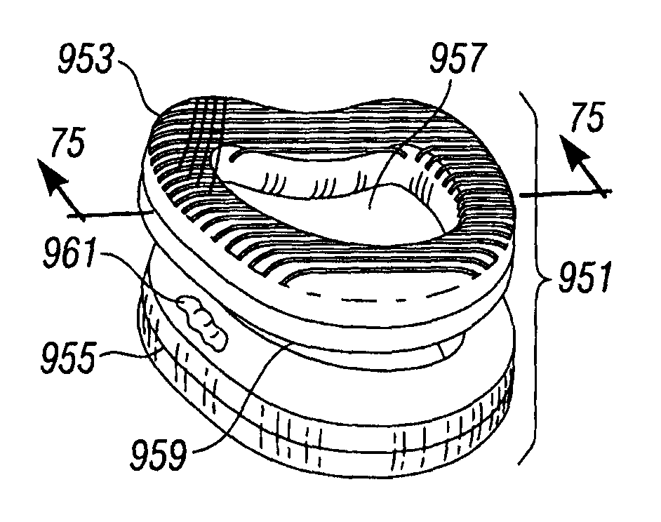
Implants, such as femoral diaphyseal rings currently used give the surgeon problems of (1) rotating in the interspace during insertion, (2) not remaining positioned properly to the surgical instrument utilized for implantation and fixation, (3) backing out of the interspace, (4) fracturing during insertion and (5) failure to achieve fusion.
No design has yet provided a solution to these problems in the allograft diaphyseal ring implant field.

Method used


Image

  • Spinal fusion instrumentation, implant and method
  • Spinal fusion instrumentation, implant and method
  • Spinal fusion instrumentation, implant and method

Examples


Embodiment Construction

[0115]The description and operation of the contained direct particle beam flow abrasion system of the present invention will be best described with reference to FIG. 1. FIG. 1 illustrates a plan exploded view of a distractor 31 of the invention as a two-piece instrument including a handle portion 33 and a tip portion 35. Dimensional markers are illustrated to correspond with one set of dimensions which have been found to be advantageous. Distractor 31 has an end 37 which has a gentle transition from sides to end 37 and has a dimensional width at the end represented by the letter “a” of about eight millimeters. The distance over which the width changes gives an idea of slope without limitation to a linear edge. A dimension “b” is preferably about twenty-five millimeters over which the width of the tip portion increases to a dimension “c” of about thirteen millimeters. This gives an aspect ratio change of the width of the tip portion 35 of five millimeters change over twenty-five mill...


PUM

PropertyMeasurementUnit
angleaaaaaaaaaa
angleaaaaaaaaaa
average diameteraaaaaaaaaa

Abstract

A system and method includes surgical instrumentation, implants, bone graft material, and measurement equipment to enable a spine fusion procedure to proceed more accurately, efficiently and safely by allowing precision measurement of the characteristics of the intervertebral space, selection of and provision of new implants, placement of an intervertebral implant, and to help overcome bone resorption all where improved healing thereafter takes place.

Description

[0001]This is a continuation-in-part of U.S. patent application Ser. No. 10 / 165,805 filed Jun. 6, 2002 now U.S. Pat. No. 7,351,244 which was a divisional of then U.S. patent application Ser. No. 09 / 545,401 filed Apr. 7, 2000, now U.S. Pat. No. 6,436,101 which is a continuation-in-part of U.S. patent application Ser. No. 09 / 416,922 filed Oct. 13, 1999 now abandoned.FIELD OF THE INVENTION[0002]The present invention relates to improvements in the field of spinal fusion to reduce the trauma and disturbance to surrounding tissues, reduce the time necessary to complete the operative procedure, increase the safety of the procedure, increase the accuracy of the procedure, provide improved instrumentation both for preparation and measurement, an improved procedure and an improved bone implant advantageously compatible with the instrumentation and procedure, both for anterior and anterolateral approaches to the spine with both open procedures as well as endoscopic procedures.BACKGROUND OF THE...

Claims


Application Information

Patent Timeline
Patent Type & Authority Patents(United States)
IPC IPC(8): A61F2/44
CPCA61F2/4465A61F2/4601A61F2/4611A61F2/4657A61F2002/30492A61F2002/30331A61F2002/30565A61F2002/30828A61F2002/4475A61F2002/4622A61F2002/4627A61F2002/4628A61F2002/4649A61F2002/4666A61F2002/4681A61F2220/0025A61F2220/0033A61F2230/0015A61F2230/0065A61F2230/0069A61F2310/00365A61F2/442A61F2002/2817A61F2002/2835A61F2002/2839A61F2002/30133A61F2002/302A61F2002/3023A61F2002/30563A61F2002/30593
Inventor HAMADA, JAMES S.
Owner HAMADA JAMES S
Why Eureka
Try Eureka