Electric motor control device, electric vehicle, and hybrid electric vehicle

a technology of electric motor and control device, which is applied in the direction of engine-driven generators, machines/engines, propulsion parts, etc., can solve the problems of overheating of the inverter, increasing the power loss of the electric motor drive, and small switching loss, so as to suppress the power loss and reduce the side band noise

Active Publication Date: 2011-04-19
AISIN AW CO LTD
View PDF18 Cites 21 Cited by
  • Summary
  • Abstract
  • Description
  • Claims
  • Application Information

AI Technical Summary

Benefits of technology

[0008]The present invention thus reduces side band noise and also suppresses a power loss, as well as achieve various other advantages.
[0009]In order to achieve the present invention described above, in providing an inverter interposed between an electric motor and a direct current power source, and controlling exchange of electric power between the electric motor and the direct current power source by switching the inverter by PWM pulses, a carrier frequency of the PWM pulses is determined to be a high frequency at which the side band noise is small when a target torque and a rotational speed of the electric motor are in a predetermined region set for suppressing the side band noise, whereas the carrier frequency is determined to be a low frequency that is lower than the high frequency and that reduces the switching loss of the inverter when the target torque and the rotational speed are outside of the predetermined region, and coil voltages, that is, phase voltages, of the electric motor are PWM-controlled so that an output torque of the electric motor coincides with the target torque.

Problems solved by technology

If the carrier frequency is increased to reduce the side band noise without changing a voltage modulation mode, the switching loss of the inverter can increase, causing an overheating of the inverter.
Moreover, a power loss of the electric motor drive increases.
JP-A-2004-289985, the two-phase modulation includes only a small number of switching operations as a total number of three-phase switching operations and also the carrier frequency of 5 kHz requires only a small number of switching operations, thus producing a small switching loss, whereas the side band noise is large.
Therefore, driving in the two-phase modulation with 5 kHz is expected to produce a small power loss but a large noise.
The three-phase modulation includes a large number of switching operations as a total number of three-phase switching operations and also the carrier frequency of 7 kHz produces a large switching loss although the noise is small.
Therefore, driving in the three-phase modulation with 7 kHz is expected to produce a small noise but a large power loss.

Method used


Image

  • Electric motor control device, electric vehicle, and hybrid electric vehicle
  • Electric motor control device, electric vehicle, and hybrid electric vehicle
  • Electric motor control device, electric vehicle, and hybrid electric vehicle

Examples


first embodiment

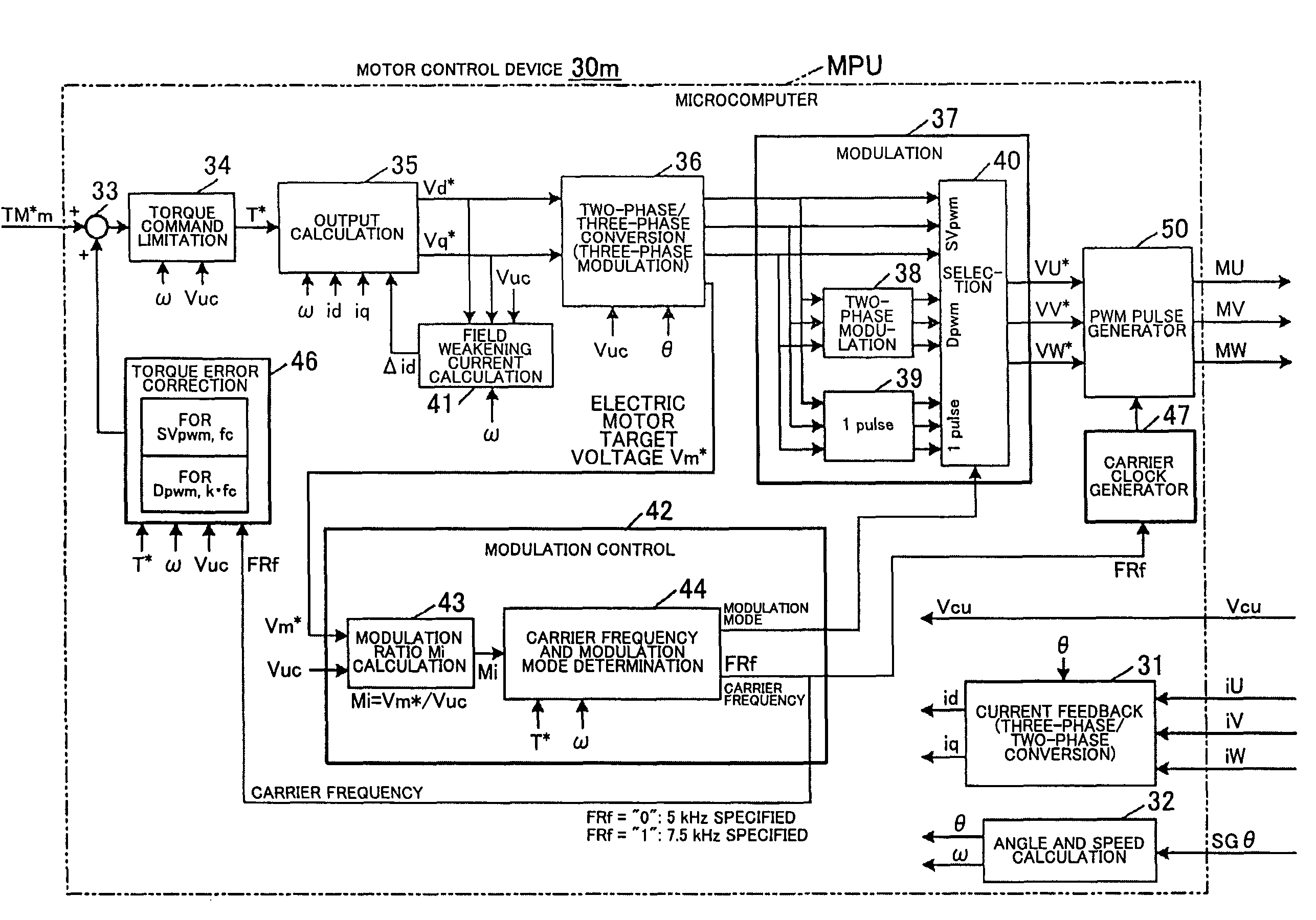
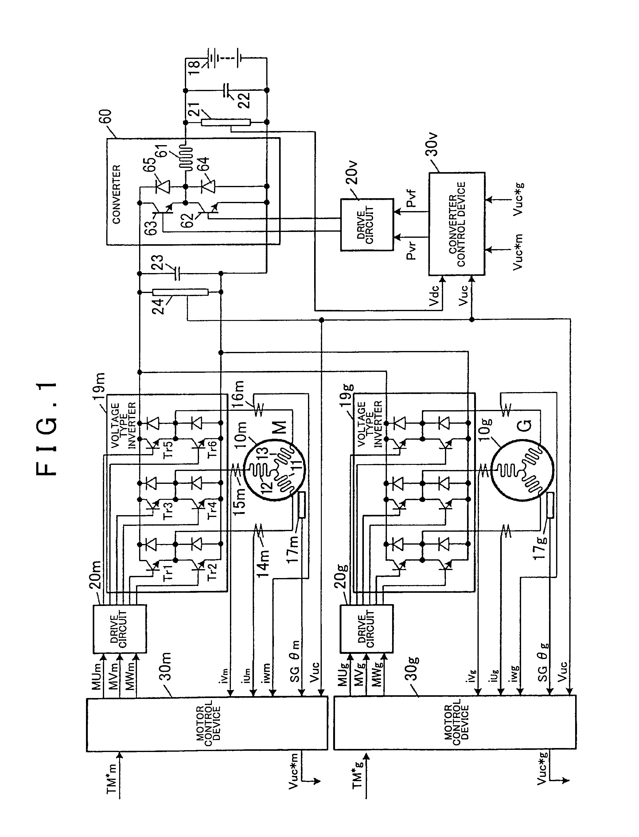
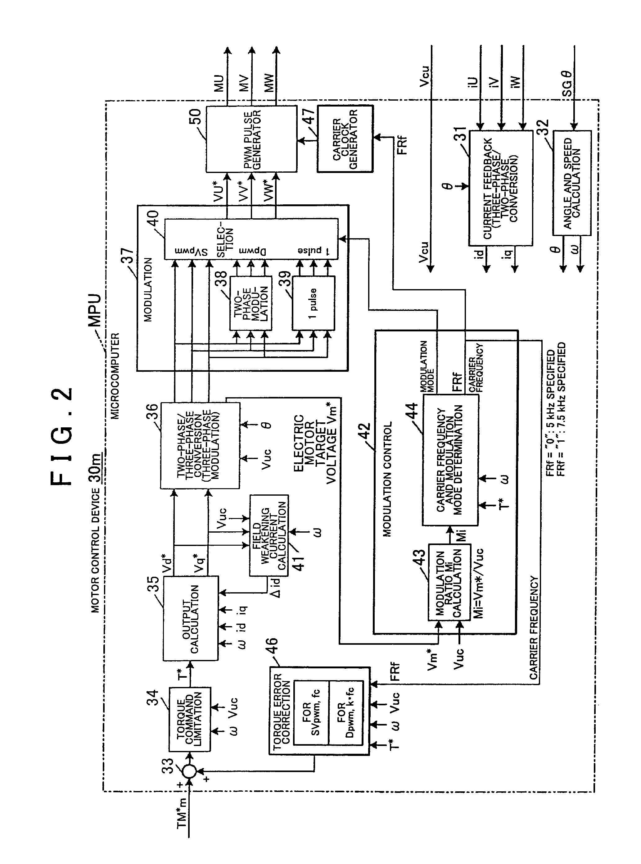
[0024]FIG. 1 shows an outline of a first embodiment of the present invention. In the present embodiment, an electric motor 10m is a permanent magnet type synchronous motor mounted on a vehicle for rotationally driving wheels. The electric motor 10m has a rotor having a permanent magnet built therein and a stator having three phase coils 11 to 13 of U-phase, V-phase, and W-phase, respectively. A voltage type inverter 19m supplies power from a battery 18 mounted on the vehicle to the electric motor 10m. A rotor of a resolver 17m for detecting a magnetic pole position of the rotor is connected to the rotor of the electric motor 10m. The resolver 17m generates an analogue voltage (rotational angle signal) SGθm representing a rotational angle of the rotor, and provides the analogue voltage to a motor control device 30m. A similar resolver 17g is used for the electric motor 10g.

[0025]When power for vehicle electrical equipment is on, a primary-side capacitor 22 is connected to the batter...


PUM


Abstract

An electric motor control device includes a direct current power source; an inverter interposed between an electric motor and the direct current power source, the inverter device controlling an exchange of electric power therebetween; an inverter control unit that generates PWM pulses having a duty ratio corresponding to voltage command signals and sends the PWM pulses to the inverter in order to switch the inverter; a frequency changing unit that changes a carrier frequency of the PWM pulses generated by the inverter control unit in a manner corresponding to a frequency control signal; and a motor control unit.

Description

INCORPORATION BY REFERENCE[0001]The disclosure of Japanese Patent Application No. 2007-285254 filed on Nov. 1, 2007 including the specification, drawings and abstract is incorporated herein by reference in its entirety.BACKGROUND[0002]The present invention relates to an electric motor control device and a hybrid drive unit.[0003]Japanese Patent Application Publication No. JP-A-7-303302 describes an electric motor drive employing a two-phase modulation system in which one phase voltage of three phase voltages applied to an electric motor is fixed at a high level or a level, and the remaining two phases are PWM-controlled. The two-phase modulation generates distortion in a waveform of the voltage applied to the electric motor, causing noise and degradation in efficiency. In order to improve these problems, Japanese Patent Application Publication No. JP-A-7-303302 presents a control system for reducing the distortion in the waveform. In addition, because the modulation becomes equivale...

Claims


Application Information

Patent Timeline
Patent Type & Authority Patents(United States)
IPC IPC(8): H02P5/00F02N11/04B60L50/13
CPCH02P6/183B60L11/123B60L11/14B60L15/025B60W10/08B60W10/26H02P6/08H02P21/00H02P21/0089H02P27/08B60K6/26B60K1/02B60L2240/421B60L2240/423B60L2270/142B60W20/00B60W2710/081B60W2710/083Y02T10/6217Y02T10/643Y02T10/7077B60L50/16B60L50/61Y02T10/62Y02T10/64Y02T10/70Y02T10/7072B60W20/20B60W2050/0002B60W2050/0054B60W2050/0057B60W2510/081
Inventor SAHA, SUBRATAFUJIWARA, ISAONISHIMURA, KEISUKEHASEGAWA, KAZUMAOONO, YOSHINORIKINUGASA, SEIICHI
Owner AISIN AW CO LTD
Why Eureka
Try Eureka