
Processing waveform-based NDE

a waveform and waveform technology, applied in the field of processing waveforms, can solve the problems of endangerment of space shuttle orbiters, crack formation, subsequent foam shedding, etc., and achieve the effect of facilitating gating and facilitating gating

Inactive Publication Date: 2011-04-26
UNITED STATES GOVERNMENT AS REPRESENTED BY THE ADMINISTATOR OF THE NAT AERONAUTICES & SPACE ADMINISTATION
View PDF27 Cites 20 Cited by
  • Summary
  • Abstract
  • Description
  • Claims
  • Application Information

AI Technical Summary

Benefits of technology

[0015]The front surface echo (FS) from the dielectric material (sample) may be of very low signal-to-noise ratio (SNR) depending on the dielectric match between air and the sample. If a good dielectric match exists, much of the terahertz energy will be transmitted into the sample. Additionally, the focal plane sensitivity of the terahertz method disclosed herein, may, for samples of nonuniform thickness, result in the front surface echo (FS) too far out of focus and thus reduces the signal to noise ratio (SNR) even further, thus limiting the thickness variation over which the method can be used. The approximate time location of FS must be known “a priori” and the wavetrain examined manually through observation of the signal on an oscilloscope trace to determine what special post-processing needs to be applied. In this way amplification and denoising the front surface signal (FS) can be achieved. Therefore, the further process steps of controlling, approximately, the spacing between the source (transceiver) and the substrate and the spacing between the source and the front surface are usually performed preliminarily if necessary. It is also necessary to know the approximate distance between the transceiver and the metal substrate.
[0028]Fusing the stored substrate echo (M″) waveform data set file, the stored back surface echo (BS) waveform data set file, and the stored front surface echo (FS) waveform data set file, together, producing a fused data file for each of the scan points, is performed by the software. Next the software facilitates viewing, interactively, an algorithm-generated amplitude display of the fused waveforms associated with all scan points for selected scan points of the sample arranged according to x and y scan coordinates.
[0030]Again, the software facilitates gating, interactively, the back surface (BS) echo waveform and gating, interactively, the substrate (M″) echo waveform of one of the fused waveform files based on ranges determined from viewing one of the selected fused waveforms. Next, a calculation of the difference in time, Δt, between the front surface (BS) echo waveforms and the substrate (M″) echo waveforms on a scan point by scan point basis is generated and stored as a Δt file. The generation of the 2τ and Δt files enables the step of determining and storing, on a scan point by scan point basis, the velocity of terahertz electromagnetic radiation in the sample without prior knowledge of the thickness of the sample. Further, generation of the 2τ and Δt files enables determining and storing, on a scan point by scan point basis, the thickness of the sample without prior knowledge of the velocity of the terahertz electromagnetic radiation in the sample.
[0035]It is an object of the present invention to provide an inspection method which allows the separation of time-of-flight variations into its microstructural and thickness components.
[0039]It is an object of the present invention to provide a computer algorithm which enables mapping of scan data arranged in an x-y matrix which provides information about the velocity / density of the sample under evaluation / test without knowing the thickness of the sample under evaluation / test.
[0040]It is an object of the present invention to provide a computer algorithm which enables mapping of scan data arranged in an x-y matrix which provides information about the thickness of the sample under evaluation / test without knowing the density of the sample under evaluation.

Problems solved by technology

Foam density variation was identified as a potential problem in which thermal expansion mismatch between areas of different density could result in crack formation, subsequent foam shedding, and endangerment of the space shuttle orbiter.
Prior to implementation of the method disclosed herein it was not possible to quantitatively measure density using a totally non-contact, non-water-coupled method.

Method used


Image

  • Processing waveform-based NDE
  • Processing waveform-based NDE
  • Processing waveform-based NDE

Examples


Embodiment Construction

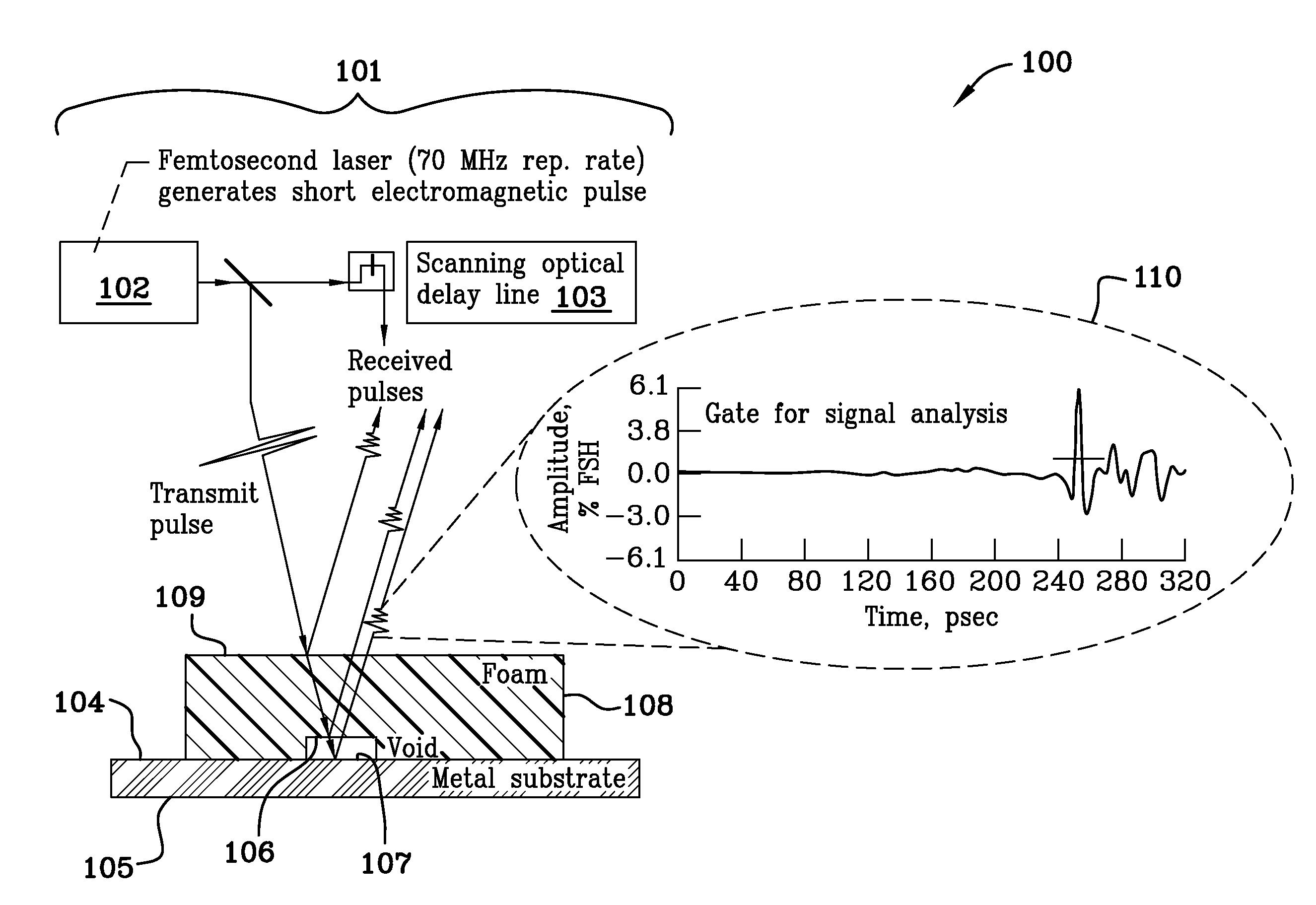
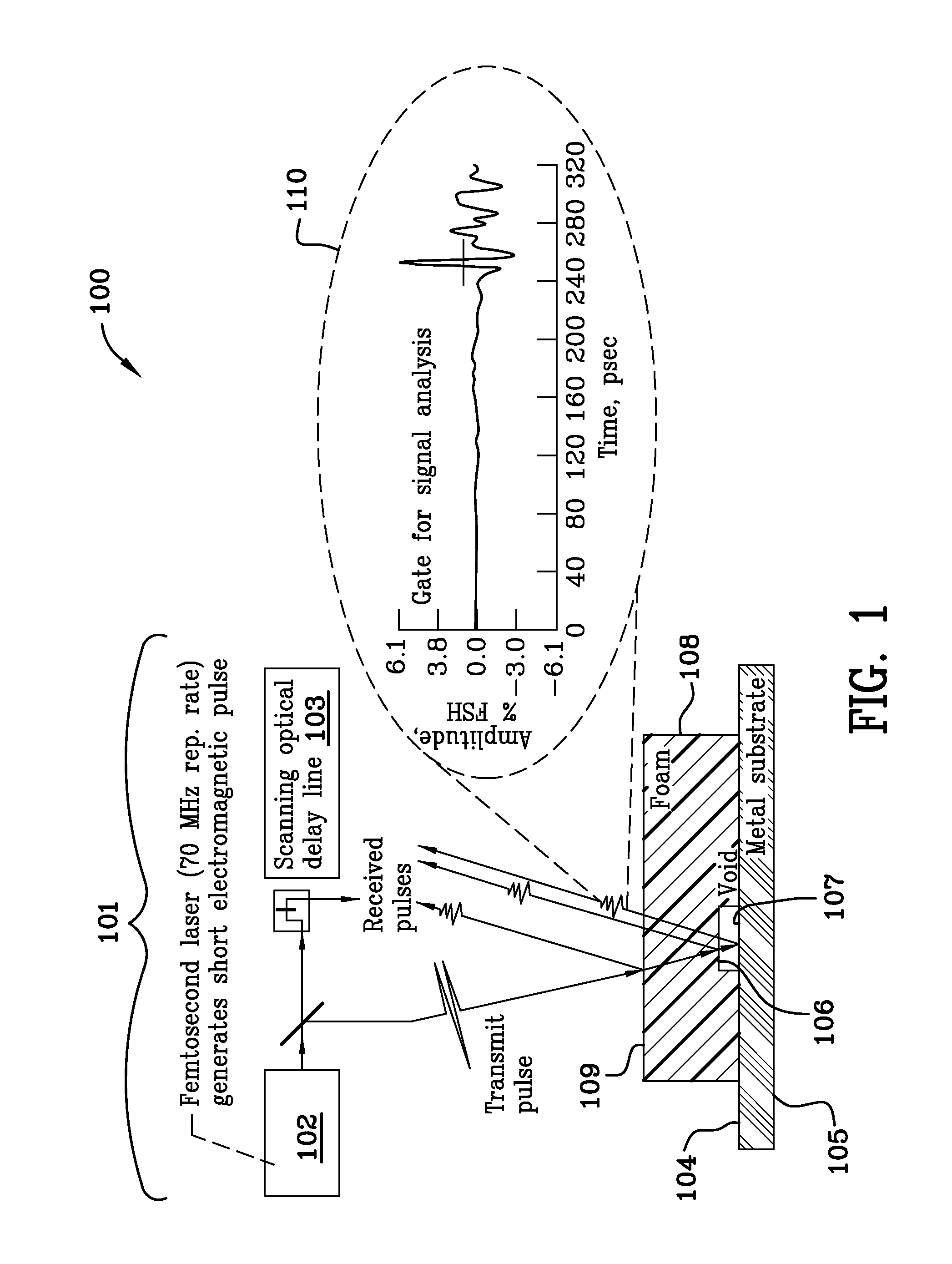
[0094]FIG. 1 is a schematic diagram 100 of the reflection-mode terahertz methodology illustrating reflections received off of the various interfaces and gating of the reflected signal. A transceiver 101 includes a femtosecond laser (70 MHZ rep. rate) 102 which generates short terahertz electromagnetic pulses and a receiver 103. Reflections will be received from the various interfaces 109, 104. Reflection from the metal substrate 104 will be the strongest. The horizontal dotted line from the echo shows a time gate 110 typically used during signal processing. The back surface 105 of the metal substrate is illustrated as is the beginning of the void 106 in the foam, silicon nitride or other dielectric 108. The void in this example terminates 107 at the front surface of the metal substrate 104. The front surface of the foam, silicon nitride or other dielectric 109 is illustrated in FIG. 1 as is a graphical depiction of a gate 110 for signal analysis.

[0095]Terahertz imaging is being used...


PUM

PropertyMeasurementUnit
wavelengthsaaaaaaaaaa
thickaaaaaaaaaa
velocitiesaaaaaaaaaa

Abstract

A computer implemented process for simultaneously measuring the velocity of terahertz electromagnetic radiation in a dielectric material sample without prior knowledge of the thickness of the sample and for measuring the thickness of a material sample using terahertz electromagnetic radiation in a material sample without prior knowledge of the velocity of the terahertz electromagnetic radiation in the sample is disclosed and claimed. Utilizing interactive software the process evaluates, in a plurality of locations, the sample for microstructural variations and for thickness variations and maps the microstructural and thickness variations by location. A thin sheet of dielectric material may be used on top of the sample to create a dielectric mismatch. The approximate focal point of the radiation source (transceiver) is initially determined for good measurements.

Description

[0001]This application is a continuation-in-part of application Ser. No. 12 / 163,382 filed Jun. 27, 2008 now U.S. Pat. No. 7,876,423. The instant application and application Ser. No. 12 / 163,382 filed Jun. 27, 2008 have the same inventor and are commonly owned by the same assignee.ORIGIN OF THE INVENTION[0002]The invention described herein was made by an employee of the United States Government, and may be manufactured and used by the government for government purposes without the payment of any royalties therein and therefor.FIELD OF THE INVENTION[0003]As a result of Space Shuttle Columbia Accident Investigation Board recommendations, an aggressive program to eliminate all External Tank Thermal Protection System debris-shedding at the source was initiated. Terahertz c-scan imaging is an emerging and very effective nondestructive evaluation (NDE) technique used for dielectric materials analysis and quality control in the pharmaceutical, biomedical, security, materials characterization...

Claims


Application Information

Patent Timeline
Patent Type & Authority Patents(United States)
IPC IPC(8): G01N21/00G01B11/28
CPCG01B11/0625G01N21/3581G01N21/3563G01J3/42
Inventor ROTH, DONALD J
Owner UNITED STATES GOVERNMENT AS REPRESENTED BY THE ADMINISTATOR OF THE NAT AERONAUTICES & SPACE ADMINISTATION
Learn More