Composite ceramic body, method of manufacturing the same and ceramic filter assembly

a technology of ceramic filter and composite ceramic, which is applied in the direction of hydrogen/synthetic gas production, inorganic chemistry, machines/engines, etc., can solve the problems of restricting the increase of porosity, and achieve the effect of restrainting crosslinking and polymerization reactions

Inactive Publication Date: 2011-05-03
NORITAKE CO LTD
View PDF25 Cites 0 Cited by
  • Summary
  • Abstract
  • Description
  • Claims
  • Application Information

AI Technical Summary

Benefits of technology

[0025]In the preferred embodiment according to the first aspect of the invention, the porous ceramic body is immersed in the polysilazane solution in the step of impregnating, and is heated in a condition that the porous ceramic body is immersed in the polysilazane solution in the step of heating. This provides proceeding in crosslinking hardening and burning of polysilazane with the polysilazane solution filled in the pores, and accordingly, provides further denser filling in the pores with polysilazane.
[0029]In the preferred embodiment according to the third aspect of the invention, the plurality of pores of the porous ceramic body are coated with a separation layer having a plurality of micro pores of which a diameter is smaller than that of the plurality of pores of the porous ceramic body. This provides a ceramic filter assembly including a plurality of different components in their roles such as a porous ceramic body, that is, a component for obtaining mechanical strength, and a separation layer, that is, a component for separation functioning, on its surface. The porous ceramic body having sufficient thicknesses for obtaining its mechanical strength, and having pores that are sufficiently large in diameter to reduce permeation resistance of the fluid may be employed. While the ceramic filter assembly according to the third aspect may be one in which the porous ceramic body functions itself as a separation layer, the above assembly is easy to be superior in both mechanical strength and fluid permeation.
[0030]More preferably, the porous ceramic body has an intermediate layer having pores of relatively small in diameter disposed on the surface of a support layer having pores of relatively large in diameter, and the separation layer is disposed on the intermediate layer. This provides the thicker support layer and larger pores in diameter with moderating the effects of the thickness of the separation layer and the diameter of the pores to be easier to be superior in both mechanical strength and fluid permeation. Upon manufacturing the ceramic filter including the separation layer having fine pores on the surface of the porous ceramic body, the sizes of the pores on the surface of the porous ceramic body is limited in accordance with the thickness of the separation layer and pores, to form the separation layer without defects. On the other hand, the porous ceramic body is required to have the sufficient thickness to obtain mechanical strength, and accordingly, smaller pores of the porous ceramic body in diameter to form a separation layer having fine pores causes nonnegligibly larger fluid permeation resistance in the porous ceramic body. The above-described embodiment permits larger pores in the support layer of the porous ceramic body in diameter to a degree negligible in fluid permeation resistance, by disposing the intermediate layer having the diameter of the pores in accordance with the diameter of the pores in the separation layer.
[0038]Preferably, the temperature in the heating treatment, that is, the temperature in the burning step is set at about 600-1300° C. in the step of heating. This permits sufficient conversion of polysilazane into Si—N—C series ceramic. The burning temperature is preferably set at the higher temperature by about not smaller than 100° C. (that is, by about 100° C. higher or further higher), than the treatment temperature upon forming the separation layer or bonding to the filter component. This preferably restrains decomposition of non-oxide ceramic generated from polysilazane even if heated in the following steps.

Problems solved by technology

Besides, restraining crosslinking and polymerization reaction permits use of polysilazane of high molecular weight, and it causes restraining, generating voids by volatilization of the solvent in drying and burning, and furthermore, it causes restraining increasing of porosity.

Method used


Image

  • Composite ceramic body, method of manufacturing the same and ceramic filter assembly
  • Composite ceramic body, method of manufacturing the same and ceramic filter assembly
  • Composite ceramic body, method of manufacturing the same and ceramic filter assembly

Examples


Embodiment Construction

[0058]Hereinafter, there will be described the present invention by reference to the drawings. The figures are appropriately simplified or transformed, and all the proportion of the dimension and the shape of a portion or member may not be reflective of the real one in the following embodiments.

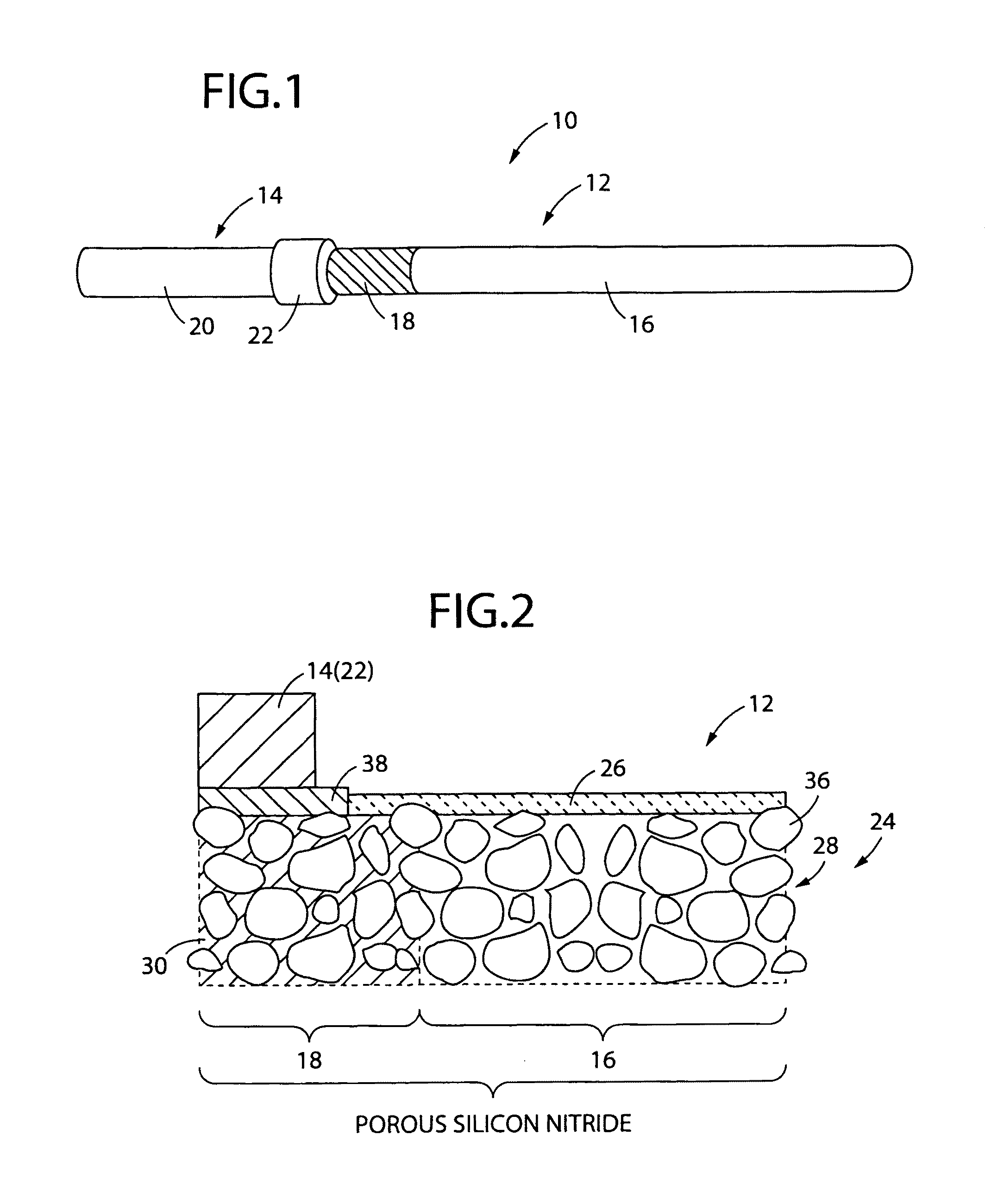
[0059]FIG. 1 illustrates a ceramic filter assembly 10 in whole of an embodiment according to the present invention in a perspective view. The assembly 10 has a tubular shape in whole having a bottom, and includes a filter 12 having an opening on the left side and a bottom to be closed on the right side in FIG. 1, and a tubular connector 14 connected to the left side and on the opening of the filter 12.

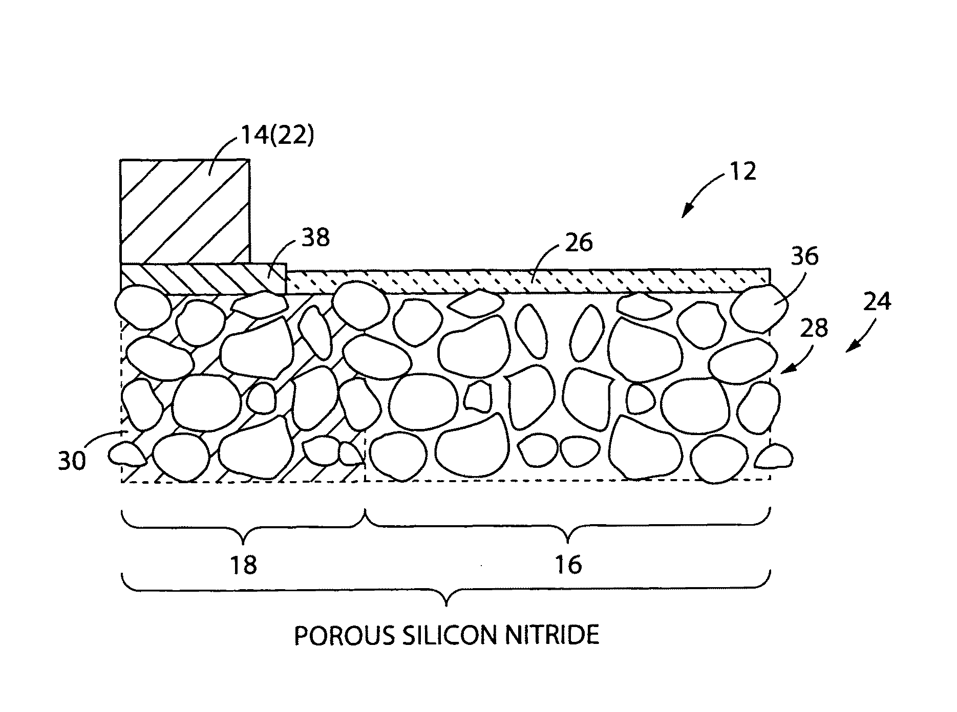
[0060]The whole filter 12 is constituted by ceramic, and includes a porous material portion 16 on the bottom side, and a dense material portion 18 on the connector 14 side of the filter 12. The area filled with oblique lines in FIG. 1 indicates the dense material portion 18. The connector 14 is ...


PUM

PropertyMeasurementUnit
temperatureaaaaaaaaaa
viscosityaaaaaaaaaa
porosityaaaaaaaaaa

Abstract

A method for manufacturing a composite ceramic body with occluding a plurality of pores that are open at its surface of a porous ceramic body, the method includes the steps of impregnating a polysilazane solution including polysilazane having a repetition structure of fundamental units of at least one of [—Si(H)(CnH2n+1)—NH—] and [—Si(CnH2n+1)2—NH—], and a predetermined organic solvent, into the plurality of pores of the porous ceramic body, and heating the porous ceramic body to convert the polysilazane in the plurality of pores into ceramic material.

Description

[0001]This application is based on Japanese Patent Application No. 2007-172120 filed Jun. 29, 2007, the contents of which are incorporated hereinto by reference.BACKGROUND OF THE INVENTION[0002]1. Field of the Invention[0003]The present invention relates to a composite ceramic body in which pores of a porous ceramic body that are opened on the surface of the porous ceramic body are occluded by another ceramic material, a method of manufacturing the same and a ceramic filter assembly.[0004]2. Description of Related Art[0005]Porous material is important and utilized in a very wide range of industrial fields such as for separation and adsorption and as a substrate for catalyst. For instance, in chemical engineering many researches and developments to improve reaction efficiencies by utilizing separation, adsorption and catalyst reactions recently and frequently proceeds using porous material in the reaction system, in the reactor for obtaining the desired production by separation and r...

Claims


Application Information

Patent Timeline
Patent Type & Authority Patents(United States)
IPC IPC(8): B01D39/06B01D24/00B01D50/00B01D39/14F01N3/00
CPCB01D67/0039B01D71/02B01D71/024C01B3/503C04B35/589C04B35/6269C04B37/026C04B41/009C04B41/5066C04B41/87B01D67/0067C04B41/4517C04B41/4535C04B41/4554C04B41/5059C04B41/526C04B35/00C04B35/584C04B38/00B01D2323/46B01D2323/28B01D2323/283B01D2323/286B01D2323/30C01B2203/0405C01B2203/0465C04B2111/00793C04B2235/6562C04B2237/125C04B2237/368B01D2325/023
Inventor MIYAJIMA, KEITAANDO, YASUNORI
Owner NORITAKE CO LTD
Why Eureka
Try Eureka