Circuit and method providing dynamic scan chain partitioning

a dynamic scan and circuit technology, applied in the direction of electronic circuit testing, measurement devices, instruments, etc., can solve the problems of scan-based testing suffering from elevated power dissipation, overheating of the chip, and reducing the efficiency of scan-based testing, so as to minimize the peak power during testing

Inactive Publication Date: 2011-05-03
KUWAIT UNIV
View PDF11 Cites 19 Cited by
  • Summary
  • Abstract
  • Description
  • Claims
  • Application Information

AI Technical Summary

Benefits of technology

[0018]Partitioning register is loaded with control data during the capture window through scan-in channels. The control data is precomputed by software, and dictates the partitioning of the scan chains. The software-based precomputation of control data aims at minimizing peak power during testing.

Problems solved by technology

Enhanced accessability, however, is reaped at the expense of increased switching activity.
As a result, scan-based testing suffers from elevated power dissipation.
High average power during testing leads to the overheating of the chip and, thus, endangers its reliability.
Excessive peak power levels, especially levels beyond which the chip can functionally operate at, may lead to an unexpected behavior of the circuit.
Consequently, observed responses differ from the expected ones, resulting in a yield loss.
While average power can be reduced by slowing down the shift clock, and thus suffering from prolonged test application time, even such an approach is of no remedy for peak power.
Thus, peak power reduction necessitates the special handling of this problematic test pattern.
Static partitioning of the scan chains, namely, the identical partitioning of chains for all the test patterns, may fail to deliver this special handling for the problematic pattern; highly toggling chains may be grouped together within the same partition, failing to deliver a significant peak power reduction.
However, a single partitioning may be incapable of evenly distributing the transitions of all the problematic patterns.
Furthermore, such a test set dependent solution would fail to comply with the standard industrial design flow, as a slight change in the design leads to the re-generation of test patterns, enforcing a costly, if feasible, re-synthesis of the clock network.
The utilization of externally controlled gates or modified scan cell designs has been shown to reduce test power drastically, albeit at the expense of functional performance degradation due to the additional gate delays introduced on functional paths.
Appropriate primary input assignments during the shift cycles help reduce transition propagation from the scan chain to the circuit under test; however, the effectiveness of such techniques is limited as circuits are typically controlled by scan chains rather than primary inputs.
However, all of the previous techniques extract test power reductions at the expense of performance degradation, possible layout constraint violations, or prolonged test application time.
Furthermore, none of these techniques alleviate the power dissipation problem in the clock network.
Furthermore, clock power dissipation is not reduced by these techniques.
The necessity to manipulate the test patterns is the major drawback in these techniques.
However, in these techniques power dissipation in the clock network is not alleviated, because with the shift clock spreading technique, instantaneous power will only be reduced by an offset between the rising edges of the shift clock.
Thus, deeper scan chains limit the applicability of this approach.
While these scan chain segmentation techniques provide reasonable average test power reductions, their effectiveness in reducing peak power may be limited depending on the distribution of transitions for a particular test pattern, which dictates the peak power within the statically constructed partitions.

Method used


Image

  • Circuit and method providing dynamic scan chain partitioning
  • Circuit and method providing dynamic scan chain partitioning
  • Circuit and method providing dynamic scan chain partitioning

Examples


Embodiment Construction

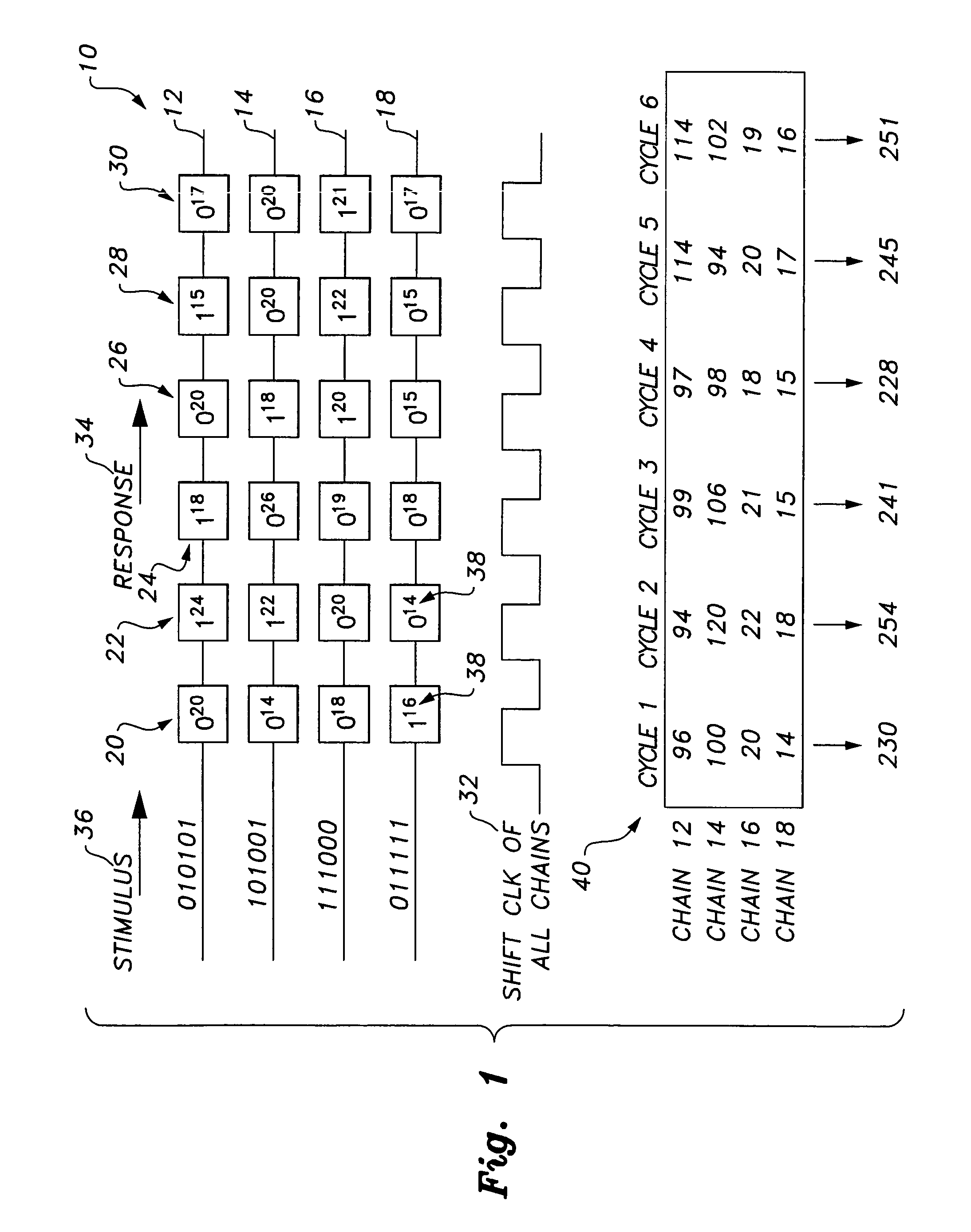
[0031]In FIG. 1, an exemplary scan test architecture, generally indicated by the number 10, for an integrated circuit chip is shown. The scan test architecture 10 shows four scan chains 12, 14, 16, 18, each with six scan cells, 20, 22, 24, 26, 28, 30. No scan chain partitioning is pursued in this example. All scan chains 12, 14, 16, 18 receive an identical shift clock 32. A captured response 34 and a subsequent stimulus 36 to be inserted are shown. A weight 38 is assigned to each of the cells 20, 22, 24, 26, 28 and is displayed in the upper right corner of each of the cell.

[0032]On the bottom of FIG. 1, a cycle-by-cycle transition count chart, generally indicated by the number 40, for each of the scan chains 12, 14, 16, 18 is also shown. For instance, in the topmost scan chain, denoted as chain 12, all the scan cells 20, 22, 24, 26, 28, 30 except for the third one, scan cell 24, toggle in the first shift cycle, resulting in 20+24+20+15+17=96 transitions in this cycle. For every shif...


PUM


Abstract

The circuit and method providing dynamic scan chain partitioning delivers peak power reduction by dynamically partitioning scan chains into multiple groups, wherein transitions are equally distributed among these multiple groups. For each test pattern, a particular partitioning that leads to the even partitioning of the transitions is computed by analyzing the transition distribution of the pattern. The scan chain partitioning is formulated using an Integer Linear Programming (ILP) and an efficient greedy heuristic. The computed information is loaded into the reconfigurable scan chain partitioning hardware during the capture window. The partitioning hardware is composed of controllable clock gating logic, which is reconfigured on a per pattern basis, wherein the reconfiguration is effected by only utilizing the existing scan channels. The reconfigurability delivers a solution that is test set independent. The results confirm the superiority of dynamic scan chain partitioning over static partitioning techniques in terms of peak power reduction.

Description

BACKGROUND OF THE INVENTION[0001]1. Field of the Invention[0002]The present invention relates to integrated circuit chip testing procedures, and particularly to a circuit and method providing dynamic scan chain partitioning to reduce power during chip testing.[0003]2. Description of the Related Art[0004]Scan-based testing has become the standard in testing VLSI circuits due to the enhanced controllability and observability it provides. High fault coverage levels can be attained by serially inserting the test stimulus into the scan chains through the scan-in pins, by applying it to the circuit, and by serially collecting the responses through the scan-out pins. Enhanced accessability, however, is reaped at the expense of increased switching activity. During the shift cycles, any scan cell may potentially toggle. Furthermore, the transitions that stem from the toggling scan cells propagate into the combinational logic being tested, triggering more transitions there. As a result, scan-...

Claims


Application Information

Patent Timeline
Patent Type & Authority Patents(United States)
IPC IPC(8): G01R31/28
CPCG06F11/267G01R31/318575
Inventor ALMUKHAIZIM, SOBEEH A.SINANOGLU, OZGUR
Owner KUWAIT UNIV
Why Eureka
Try Eureka