Fuel reformer and method for producing the same, electrode for use in electrochemical device, and electrochemical device

a fuel reformer and fuel technology, applied in the direction of metal/metal-oxide/metal-hydroxide catalysts, final product manufacturing, metal/metal-oxides/metal-hydroxide catalysts, etc., can solve the problem of unsuitable use of hydrogen storage alloys, difficulty in achieving methanol concentration, and difficulty in the whole system to achieve a weight energy density far larger than that of a conventional secondary battery. achieve the effect of reducing the cost o

Active Publication Date: 2011-05-17
MURATA MFG CO LTD
View PDF18 Cites 2 Cited by
  • Summary
  • Abstract
  • Description
  • Claims
  • Application Information

AI Technical Summary

Benefits of technology

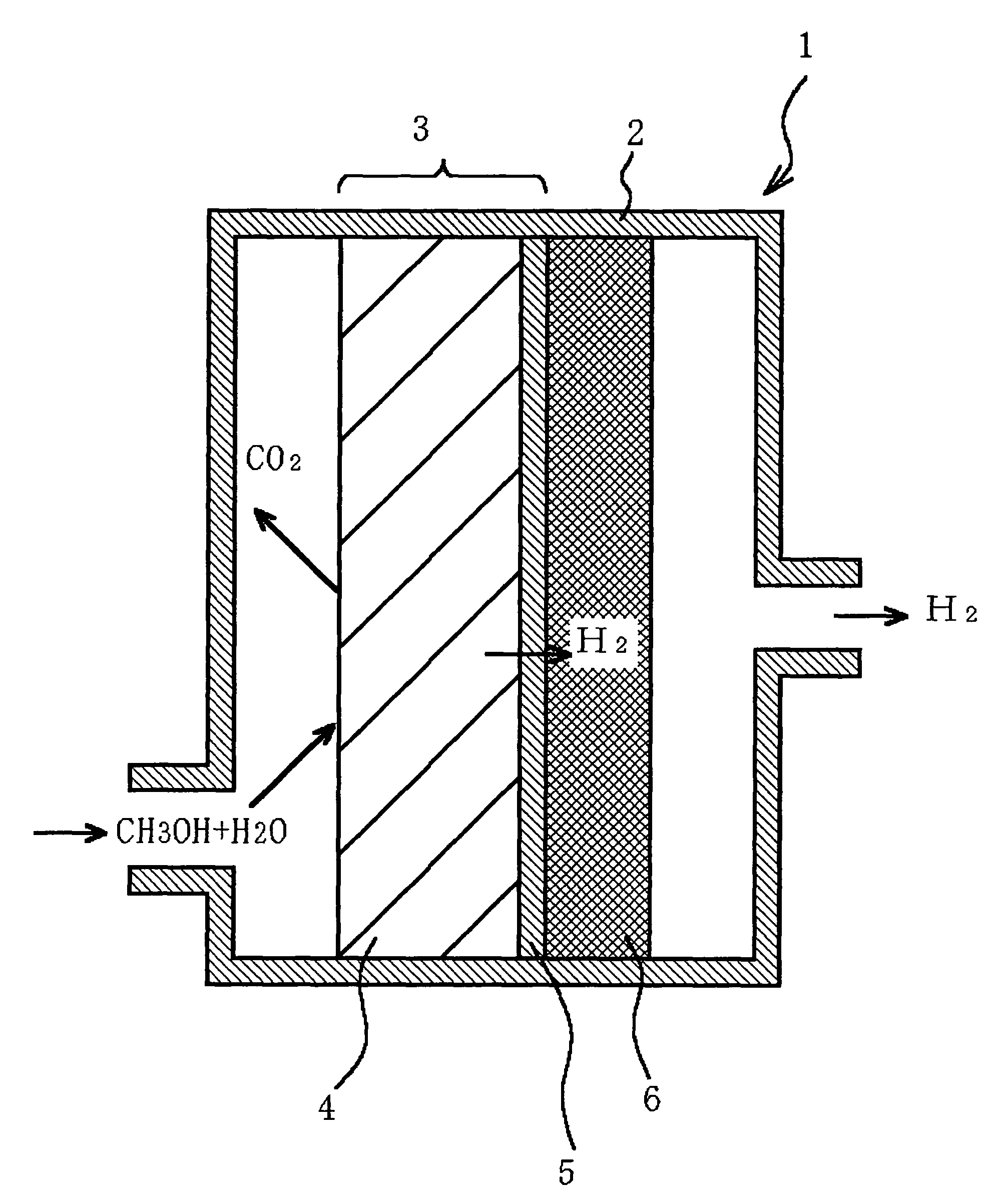
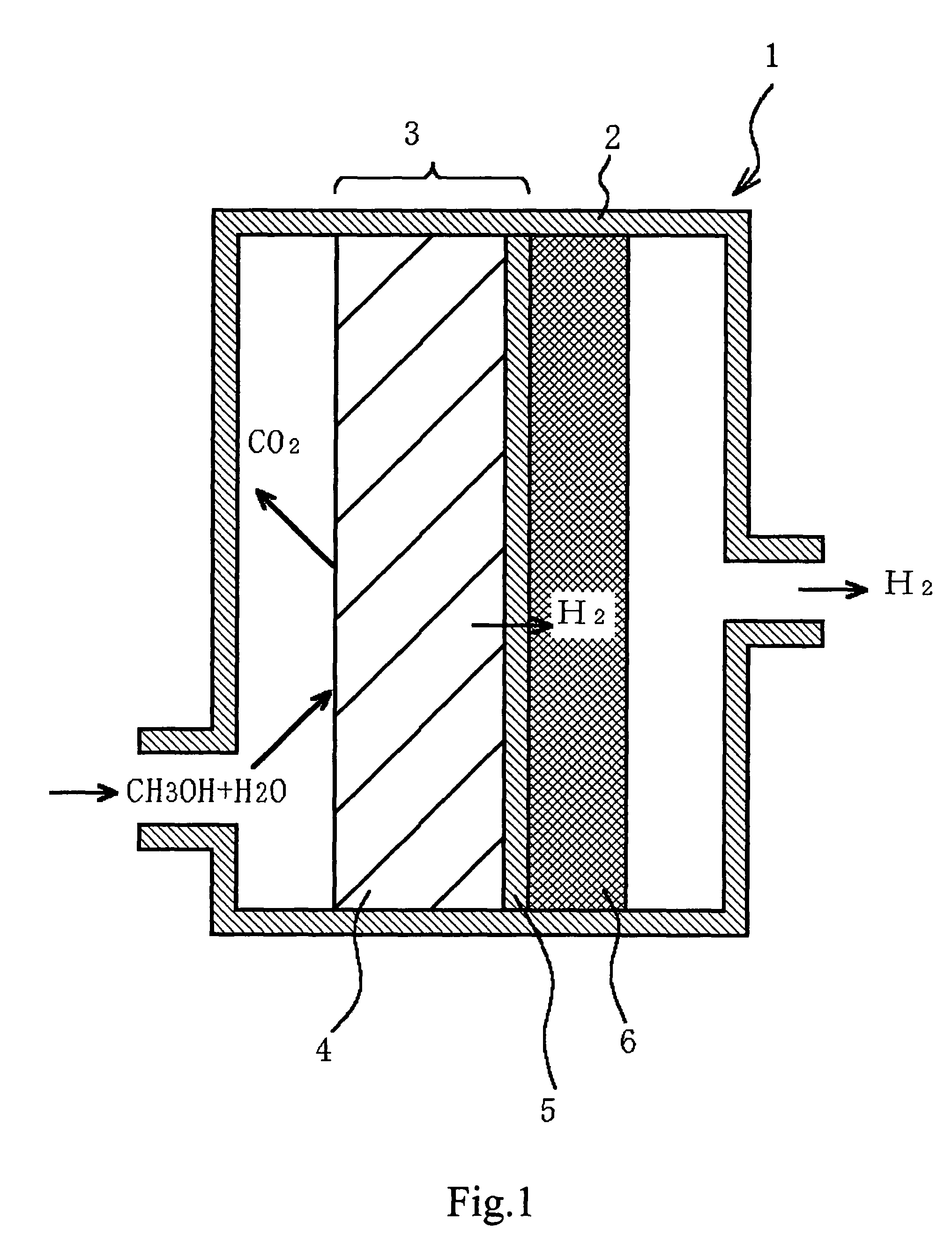
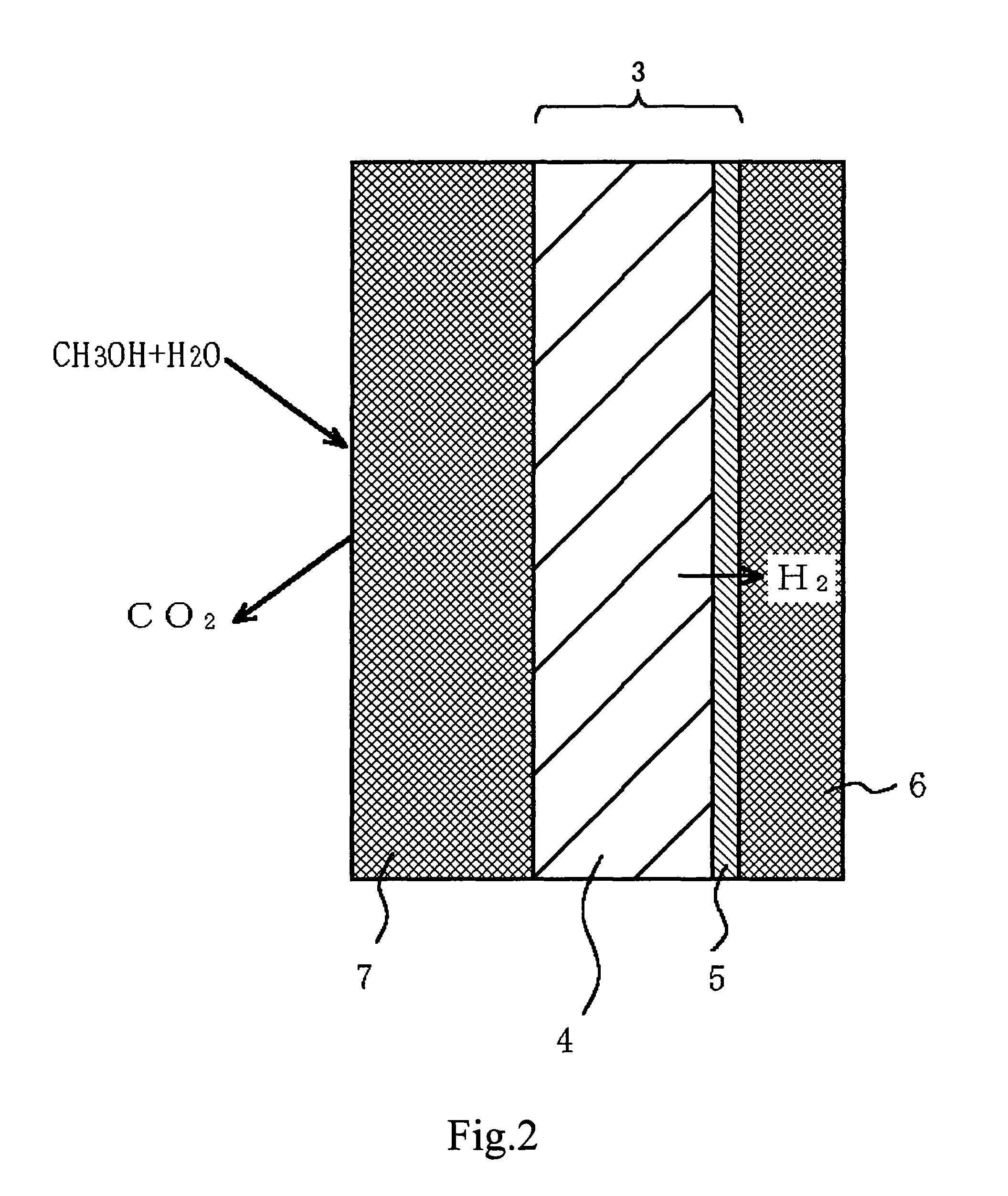
[0010]In an embodiment, the present invention provides a fuel reformer which can easily achieve high weight energy density and high volume energy density, and a method for producing the fuel reformer with ease and high efficiency as well as an electrode for an electrochemical device, such as a fuel cell, and an electrochemical device.
[0012]In the fuel reformer of the present invention in an embodiment, the above-mentioned liquid fuel (e.g., methanol and water) is supplied to the above-mentioned catalyst layer in the above-mentioned reformer and the above-mentioned liquid fuel is reformed by the above-mentioned catalyst layer into hydrogen gas, and the hydrogen is fed through the above-mentioned hydrogen permeable layer to, for example, an electrochemical device where desired electrochemical energy can be obtained. The liquid fuel is reformed into hydrogen before being fed to the electrochemical device in this way and therefore, even if the liquid fuel having a high concentration is fed to the reformer, liquid, such as methanol, is blocked by the above-mentioned hydrogen permeable layer and hence satisfactorily prevented from penetrating into the above-mentioned electrochemical device, so that power output can efficiently be obtained.
[0013]Therefore, especially when the reformer is provided independently of the electrochemical device, the above-mentioned liquid fuel can be supplied in a high concentration and efficiently reformed by the system having a simplified structure, and further the liquid can be prevented from penetrating through the electrochemical device, and thus a fuel reformer having both high weight energy density and high volume energy density can be easily realized.
[0017]Therefore, the above-mentioned hydrogen permeable layer can be obtained as a thin film which is such dense and smooth that the film is impermeable to liquid, and which has such a small thickness that the film is permeable to hydrogen without a need to increase the film strength to a large extent, and further the above-mentioned hydrogen permeable layer is formed to be integrated with the above-mentioned catalyst layer for reforming the above-mentioned liquid fuel, and thus a fuel reformer connectable to the above-mentioned electrochemical device can be produced with ease and high efficiency.

Problems solved by technology

In a case where hydrogen stored in the hydrogen storage alloy is used in the fuel cell for a small-size apparatus, because of the weight of the hydrogen storage alloy, it is difficult for the whole of the system to achieve a weight energy density far larger than that of a conventional secondary battery.
For this reason, in a case of expecting a fuel cell to exhibit a high weight energy density, the use of the currently used hydrogen storage alloy is unsuitable.
In the direct methanol method, a mixture of methanol and water in a 1:1 ratio (molar ratio) theoretically serves as a fuel, but an ionic conductor is disadvantageously permeable to methanol and hence it is generally difficult to achieve such a methanol concentration, and, in practice, methanol is diluted to be in a concentration as small as 1 mol / l and then supplied to the MEA.
However, in this method, methanol and water must be fed individually with high accuracy, making a liquid feeding system complicated, and hence this method is not suitable for further miniaturization of the system.
However, in a case where a base material for the reformer is prepared by micro-fabrication of Si or the like as already proposed, the fabrication process is complicated, increasing the cost.
Further, the reforming system provided independently of the MEA causes the volume to be larger.

Method used


Image

  • Fuel reformer and method for producing the same, electrode for use in electrochemical device, and electrochemical device
  • Fuel reformer and method for producing the same, electrode for use in electrochemical device, and electrochemical device
  • Fuel reformer and method for producing the same, electrode for use in electrochemical device, and electrochemical device

Examples


example 1

[0127]A fluororesin and carbon powder were kneaded together in an aqueous solution to prepare a coating composition. The coating composition was applied to a porous carbon sheet, and then heated in an inert gas to a softening temperature of the resin or higher to form a water-repellent carbon coated layer on the carbon sheet as a gas diffusion layer.

[0128]Next, a Pt—Ru alloy catalyst carried on carbon was kneaded with an ionic conductor, such as perfluorosulfonic acid, to prepare a coating composition. The coating composition was applied to the above-described carbon sheet having the gas diffusion layer thereon to form a catalyst electrode for a fuel electrode. The coating weight was adjusted so that the Pt—Ru amount became 0.5 mg / cm2.

[0129]Similarly, a Pt catalyst carried on carbon was kneaded with an ionic conductor, such as perfluorosulfonic acid, to prepare a coating composition, and the coating composition was applied to another carbon sheet having the gas diffusion layer there...

example 2

[0137]A Pt—Ru alloy catalyst carried on carbon was kneaded with an ionic conductor, such as perfluorosulfonic acid, to prepare a coating composition, and the coating composition was applied to a PTFE (polytetrafluoroethylene) sheet called Teflon (registered trademark) and dried. Similarly, a Pt catalyst carried on carbon was kneaded with an ionic conductor, such as perfluorosulfonic acid, to prepare a coating composition, and the coating composition was applied to a PTFE sheet and dried.

[0138]The thus prepared catalyst electrode for the oxygen electrode and catalyst electrode for the fuel electrode were disposed on both sides of an ionic conductor film, such as a perfluorosulfonic acid film, and bonded together under pressure by means of a heated press, and then the above-mentioned PTFE sheets were peeled off, namely, in accordance with a so-called decalcomania process to produce an MEA for fuel cell.

[0139]Then, a reformer produced in a similar manner as in Example 1 was connected t...

example 3

[0143]A fluororesin and carbon powder were kneaded together in an aqueous solution to prepare a coating composition. The coating composition was applied to a porous carbon sheet, and then heated in an inert gas to the softening temperature of the resin or higher to form a water-repellent carbon coated layer on the carbon sheet as a gas diffusion layer.

[0144]Next, a Pt—Ru alloy catalyst carried on carbon was kneaded with an ionic conductor, such as perfluorosulfonic acid, to prepare a coating composition. The coating composition was applied to a carbon sheet having the gas diffusion layer thereon to form a catalyst electrode for a fuel electrode. The coating weight was adjusted so that the Pt—Ru amount became 0.5 mg / cm2.

[0145]Similarly, a Pt catalyst carried on carbon was kneaded with an ionic conductor, such as perfluorosulfonic acid, to prepare a coating composition, and the coating composition was applied to a carbon sheet having the gas diffusion layer thereon to form a catalyst ...


PUM

PropertyMeasurementUnit
thicknessaaaaaaaaaa
thicknessaaaaaaaaaa
thicknessaaaaaaaaaa

Abstract

A fuel reformer which can easily achieve high weight energy density and high volume energy density, and a method for producing the fuel reformer with ease and high efficiency as well as an electrode for electrochemical device, such as a fuel cell, and an electrochemical device are provided. The present invention is to feed hydrogen obtained from a fuel reformer having a catalyst layer containing Pt for taking out hydrogen from a liquid fuel, such as methanol, and a hydrogen permeable layer, such as a Pd thin film, which is impermeable to liquid and permeable to hydrogen to an electrochemical device such as a fuel cell, which comprises a negative electrode, a positive electrode and a proton conductive film sandwiched therebetween. The present invention provides a method of producing the hydrogen permeable layer in the reformer by forming the hydrogen permeable layer and the catalyst layer on a base layer comprising Al or the like, and removing the base layer by dissolution.

Description

CROSS REFERENCES TO RELATED APPLICATIONS[0001]The present application claims priority to Japanese Patent Document Nos. P2002-151723 filed on May 27, 2002, P2002-151724 filed on May 27, 2002; and P2003-133198 filed on May 12, 2003 the disclosures of which are herein incorporated by reference.BACKGROUND OF THE INVENTION[0002]The present invention relates to a fuel reformer for obtaining hydrogen from a liquid fuel and a method for producing the fuel reformer, an electrode for use in an electrochemical device, and an electrochemical device, such as a fuel cell.[0003]As a fuel for a fuel cell for use in automobile, pure hydrogen compressed and contained in a cylinder is mainly studied. On the other hand, as a fuel for a fuel cell for use in stationary apparatus, such as a cogeneration system, reformed gas obtained from methane gas or the like is studied. With respect to the fuel for fuel cell for use in small-size apparatus, methods using hydrogen stored in a hydrogen storage alloy or u...

Claims


Application Information

Patent Timeline
Patent Type & Authority Patents(United States)
IPC IPC(8): H01M4/86B01D69/02B01D53/22B01D71/02B01J8/00B01J8/02B01J19/00B01J23/40B01J37/02C01B3/32C01B3/38C01B3/50C01B3/56H01M4/92H01M4/94H01M8/06H01M8/10
CPCB01J8/009C01B3/323C01B3/505H01M4/8605H01M4/94H01M8/0625H01M8/0662B01J8/0207B01J31/0218B01J23/40B01J37/0219C01B2203/0233C01B2203/041C01B2203/0475C01B2203/066C01B2203/107C01B2203/1223H01M4/921Y02E60/523Y02E60/50Y02P20/52Y02P70/50
Inventor KATORI, KENJI
Owner MURATA MFG CO LTD
Why Eureka
Try Eureka