Solar heat transfer apparatus

a heat transfer apparatus and solar energy technology, applied in electrical apparatus, photovoltaics, semiconductor devices, etc., can solve the problems of weakening the life and efficiency of electronic devices and systems, and achieve the effects of reducing the effectiveness of heat sources, facilitating heat source placement, and increasing mechanical stress and strain of neighboring components

Inactive Publication Date: 2011-06-07
OLANTRA FUND X L L C
View PDF12 Cites 14 Cited by
  • Summary
  • Abstract
  • Description
  • Claims
  • Application Information

AI Technical Summary

Benefits of technology

[0005]It is a major object of the invention to provide highly compact, and highly efficient, low cost, high rate solar cell heat transport apparatus, and characterized by:
[0009]Another object is to provide for low cost high rate heat transport via a coaxial tube arrangement that creates a pressure vessel with an elongate annular chamber containing a microchannel array and fluid or fluids that undergo evaporation near heat sources placed on or near regions on the outside and / or inside of the vessel and condensation in regions remote from the heat sources.
[0010]A further object is to provide a heat transport vessel that includes metal tubes with a woven metal mesh therebetween. The metal mesh serves to maintain a space between the vessel's inner and outer tubes, and acts as an extended surface for increased thermal conductivity between the fluid and the tubes between the inner and outer tubes, the mesh also providing increased area for evaporation regions. In addition, the tube surfaces adjoining or adjacent the mesh may have surface modification such as contra-helical grooves and / or abraded surfaces inter alia to enhance heat transport. Usable materials include aluminum and copper for the tubes, meshes, and extended surfaces, and hydrocarbons, fluorocarbons, and water based mixtures for working fluids. Aluminum and propane represent a cost effective combination of materials.
[0013]An added object is to provide an improved heat pipe that overcomes difficulties encountered in heat pipe use, such as difficulty in ensuring exactly horizontal orientation. A heat pipe slightly inclined from the horizontal accumulates liquid in the lower end reducing effectiveness for heat sources in regions distant from the lower end. In dynamic environments the liquid may slosh from end to end and prevent consistent operation and additionally cause an increase in mechanical stress and strain of neighboring components. The present invention overcomes these problems by confining the operating fluids to a microchannel array as in a mesh where the fluids are more affected by local forces than gravitational and inertial forces, and thus facilitate heat source placement anywhere along the length of the vessel to have consistent operation.
[0014]Fluid motion in the apparatus of the present invention may be completely or partly annular as in the case of a line like elongated heat source, and provide consistent operation along its length; or provide for both annular and axial fluid motion as in the case of discrete heat sources along its length. The vessel may have extended surfaces formed or attached for increased air side or external heat transport and these may take the form of annular metal discs or helicoids. Also, the consolidated tube / mesh / tube combination provides a useful structural product in its own right. It provides higher stiffness / mass than a comparably sized solid tube and may be used as the primary structural element in many applications. The interior or innermost region of the vessel may be used for purposes including air flow cooling and power conversion system placement.

Problems solved by technology

The lifetime and efficiency of electronic devices and systems degrade strongly with increasing temperature.

Method used


Image

  • Solar heat transfer apparatus
  • Solar heat transfer apparatus
  • Solar heat transfer apparatus

Examples


Embodiment Construction

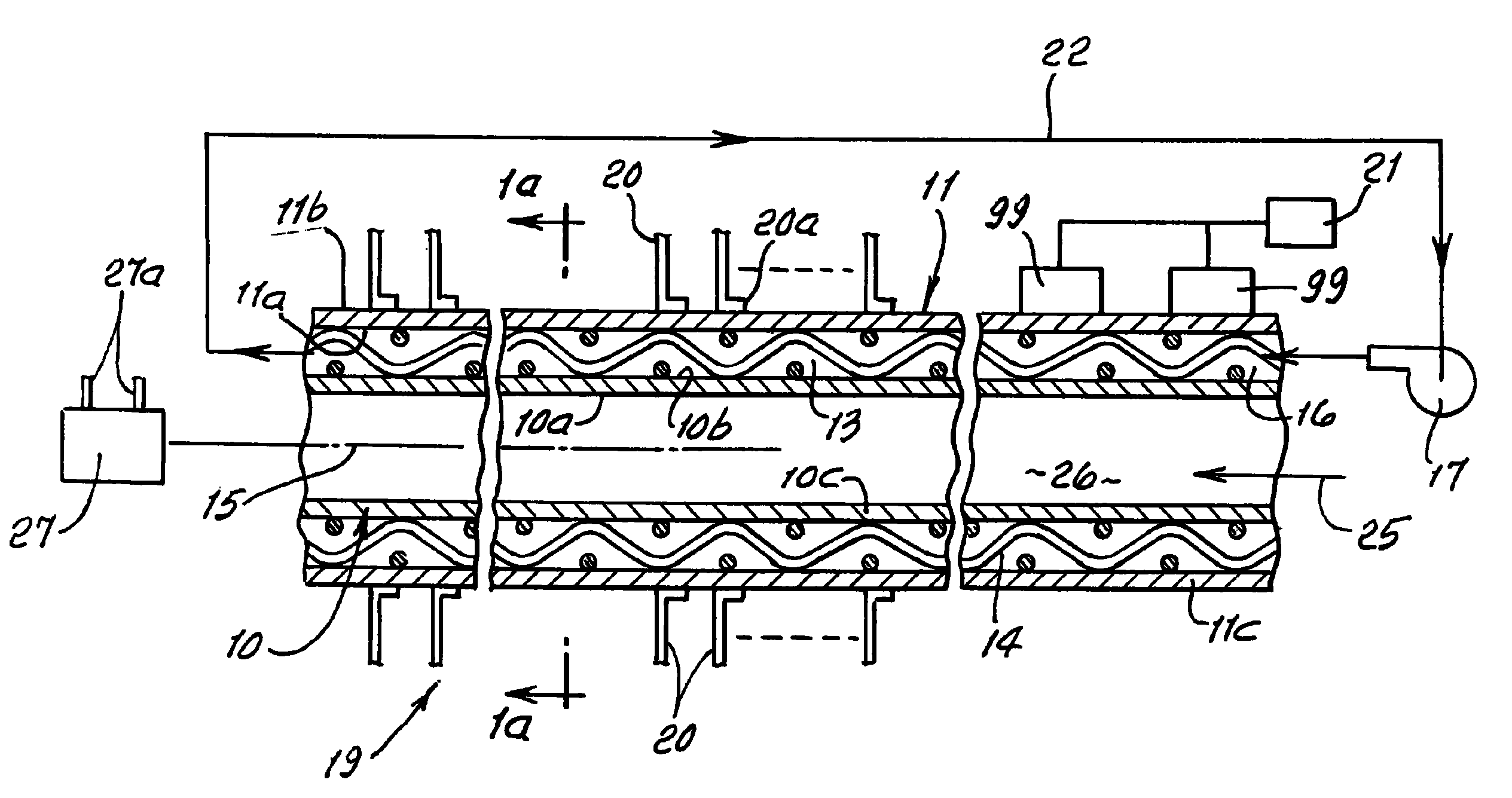
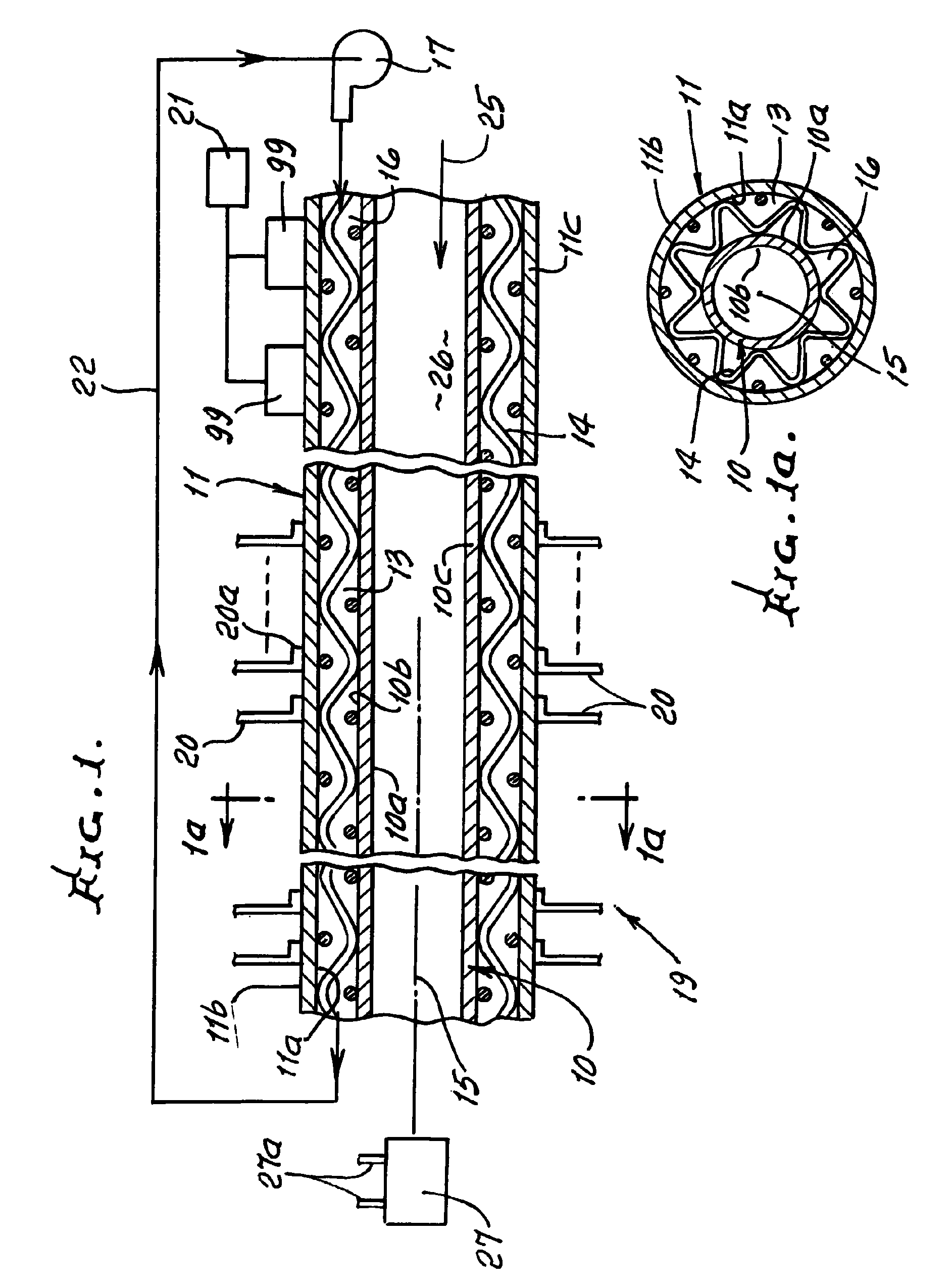
[0027]Referring first to FIGS. 1 and 1a, inner and outer bodies, as for example tubes 10 and 11 extend coaxially. Body 10 has inner and outer cylindrical surfaces 10a and 10b, and body 11 has inner and outer surfaces 11a and 11b. The bodies define space 13 therebetween which is annular. At least one of the bodies is heat conductive, for example metallic, or preferably both are metallic.

[0028]Heat conductive woven metallic mesh 14 extends in space 13, at least part way about axis 15, and extending in heat transfer relation with at least one of the bodies. For example, the mesh may contact outer surface 10b of body 10, and / or inner surface 11a of body 11, whereby heat is conducted to the mesh via one or both bodies 10 and 11. The mesh in turn transfers heat to fluid 16 in space 13, and typically flowing axially in that space, through the interstices of the mesh woven wires or strands.

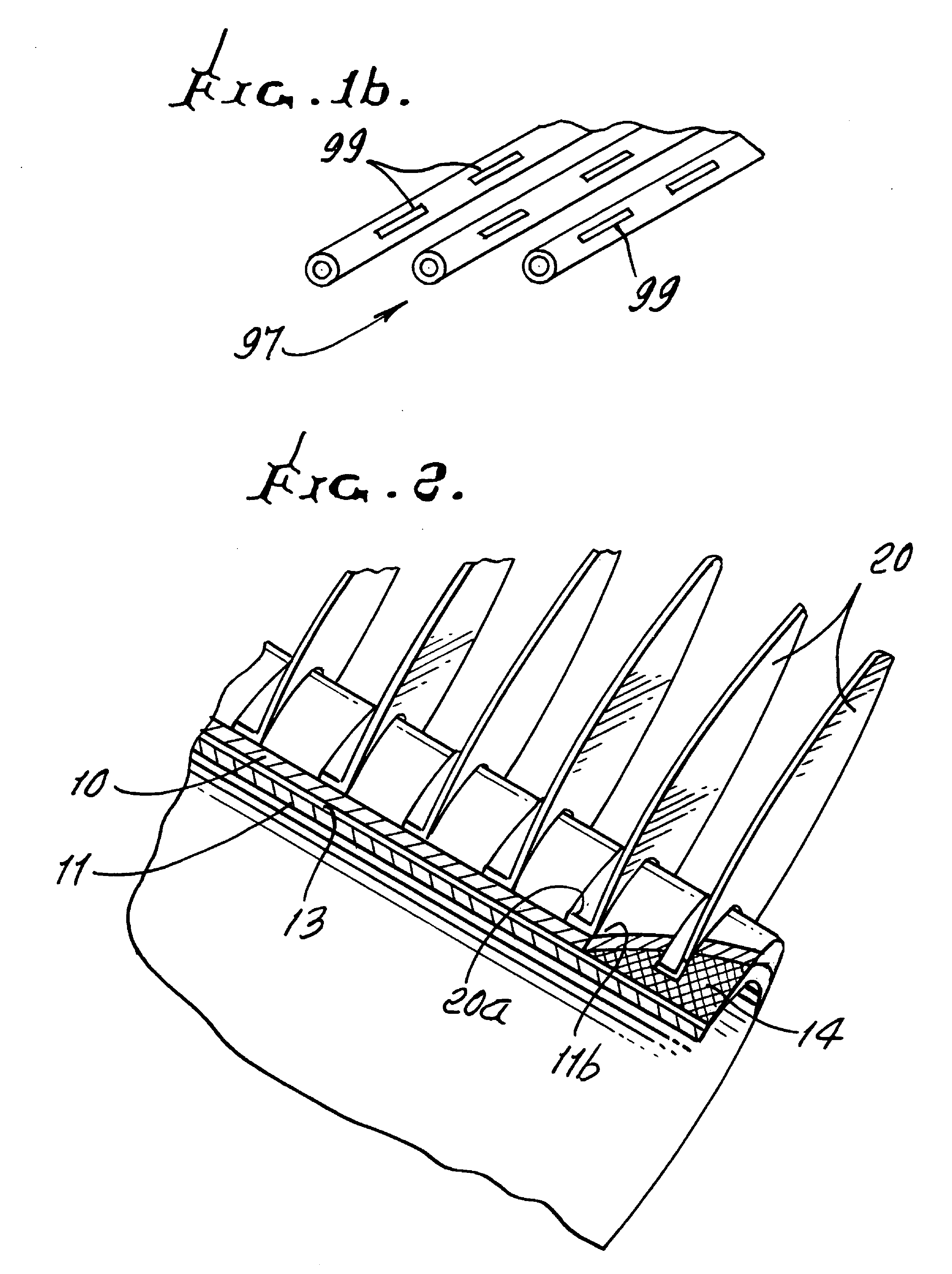
[0029]A heat generating electrical circuit element or elements, such as solar cells, is or are provide...


PUM


Abstract

Heat transfer apparatus comprising, in combination inner and outer bodies defining a space therebetween which extends at least part way about an axis, at least one of the bodies being heat conductive, a heat conductive woven mesh extending in the space at least part way about the axis, and in heat transfer relation with at least one of the bodies, fluid in the space in heat transfer contact with the mesh, and solar cells carried by the outer body.

Description

[0001]This application is based on provisional application Ser. No. 60 / 918,449, filed Mar. 15, 2007 entitled “Concentric Tube Heat Spreader”.BACKGROUND OF THE INVENTION[0002]This invention relates generally to high rate heat transport, and more specifically to such heat transport employing heat conductive woven mesh in a fluid flow path that extends about an axis, enabling highly efficient cooling of heat generating devices.[0003]The lifetime and efficiency of electronic devices and systems degrade strongly with increasing temperature. Means to transport heat from the electronic devices and systems to the local environment more effectively would allow operation of electronic devices at higher power density and thereby offer potential reductions in cost, mass, and volume.[0004]There is need for such means, as exemplified by the apparatus and its operation, producing unusual results, as disclosed herein.SUMMARY OF THE INVENTION[0005]It is a major object of the invention to provide hig...

Claims


Application Information

Patent Timeline
Patent Type & Authority Patents(United States)
IPC IPC(8): H01L31/024
CPCH01L31/0521Y02E10/50
Inventor POPOVICH, JOHN M.
Owner OLANTRA FUND X L L C
Why Eureka
Try Eureka