Supercharge Your Innovation With Domain-Expert AI Agents!

System and method for reducing particles and contamination by matching beam complementary aperture shapes to beam shapes

a beam shape and aperture shape technology, applied in the field of ion implantation systems, can solve problems such as unfavorable beam interceptions

Active Publication Date: 2011-07-12
AXCELIS TECHNOLOGIES
View PDF13 Cites 2 Cited by
  • Summary
  • Abstract
  • Description
  • Claims
  • Application Information

AI Technical Summary

Benefits of technology

The invention is about an ion implantation system and a method for reducing particles and contamination. The system includes an ion source, a mass analyzer, and a resolving assembly with a beam complementary aperture. The method involves selecting the ion beam source parameters, mass analyzer parameters, and resolving aperture position. The system measures key ion beam factors and can adjust them if needed. The technical effects of the invention include improved beam quality, reduced particles and contamination, and improved process control.

Problems solved by technology

These apertures typically cause some uneven beam intercept as the beam passes through the openings.

Method used


Image

  • System and method for reducing particles and contamination by matching beam complementary aperture shapes to beam shapes
  • System and method for reducing particles and contamination by matching beam complementary aperture shapes to beam shapes
  • System and method for reducing particles and contamination by matching beam complementary aperture shapes to beam shapes

Examples


Embodiment Construction

[0019]The present invention will now be described with reference to the drawings wherein like reference numerals are used to refer to like elements throughout, and wherein the illustrated structures are not necessarily drawn to scale.

[0020]A system and method in accordance with the present invention for reducing particles and contamination by matching a beam complementary aperture to the actual measured / determined ion beam shape. In other words, the beam complementary aperture corresponds to the beam cross-sectional envelope or substantially matches the beam cross-section; wherein the plane of the beam complementary aperture is perpendicular to the ion beam path axis.

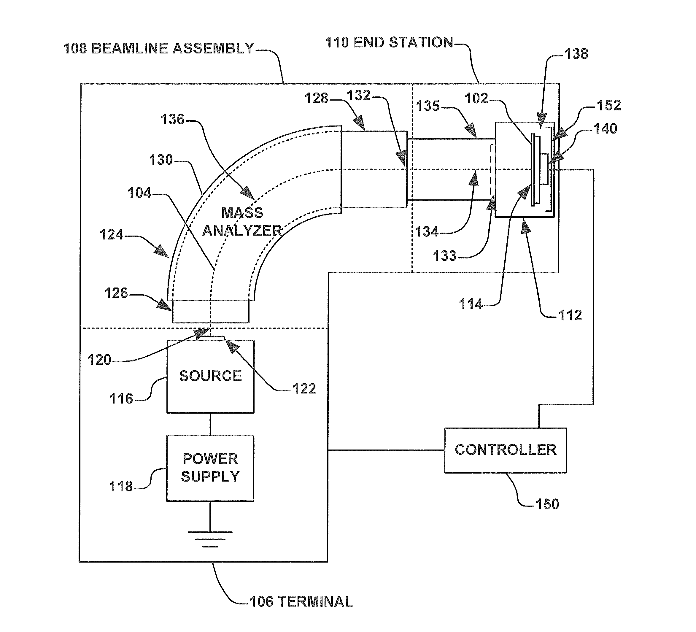
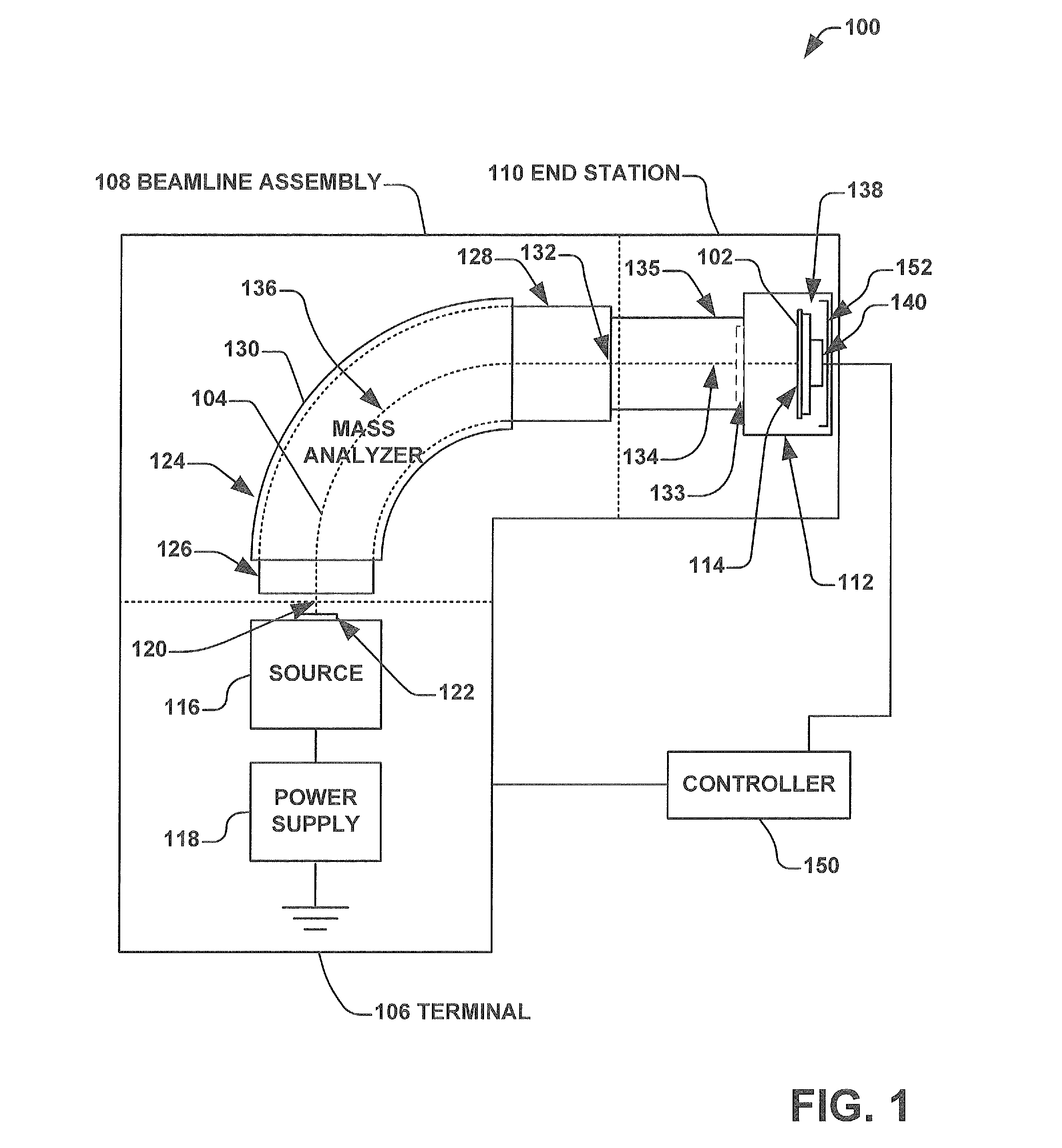
[0021]Now turning to FIG. 1, demonstrated is an example ion implantation system 100 in accordance with an aspect of the present invention for treatment of one or more workpieces. The system 100 makes use of a beam complementary aperture 133 and is presented for illustrative purposes and it is appreciated that aspects of...


PUM


Abstract

An ion implantation system comprising an ion source configured to generate an ion beam along a beam path, a mass analyzer is located downstream of the ion source wherein the mass analyzer is configured to perform mass analysis of the ion beam and a beam complementary aperture located downstream of the mass analyzer and along the beam path, the beam complementary aperture having a size and shape corresponding to a cross-sectional beam envelope of the ion beam.

Description

FIELD OF THE INVENTION[0001]The present invention relates generally to ion implantation systems, and more specifically to a system and method for reducing particles and contamination by matching beam defining aperture shapes to ion beam shapes in the ion implantation systems.BACKGROUND OF THE INVENTION[0002]In the manufacture of semiconductor devices, ion implantation is used to dope wafers and / or workpieces with impurities or dopants. Ion beam implanters are used to treat silicon workpieces with an ion beam, in order to produce n or p type extrinsic material or to form passivation layers during fabrication of an integrated circuit. When used for doping semiconductors, the ion beam implanter injects selected extrinsic ion specie to produce the desired semiconducting material. Implanting ions generated from source materials such as antimony, arsenic or phosphorus results in “n type” extrinsic material workpieces, whereas if “p type” extrinsic material workpieces are desired, ions gen...

Claims


Application Information

Patent Timeline
Patent Type & Authority Patents(United States)
IPC IPC(8): H01J49/00
CPCH01J37/04H01J37/05H01J37/244H01J2237/022H01J2237/0455H01J2237/24507H01J2237/24542H01J2237/24578H01J37/317
Inventor GRANT, JOHN FRANCISSPLINTER, PATRICK RICHARD
Owner AXCELIS TECHNOLOGIES
Features
  • R&D
  • Intellectual Property
  • Life Sciences
  • Materials
  • Tech Scout
  • Unparalleled Data Quality
  • Higher Quality Content
  • 60% Fewer Hallucinations
Learn More