Ultra-low friction air pump for creating oscillatory or pulsed jets

a technology of oscillatory or pulsed jets and air pumps, applied in the field of aerodynamic surfaces, can solve the problems of mechanical control surfaces, limited ability to respond quickly and efficiently, and add complexity to aerodynamic devices, and achieve novel design, easy to scale in size, and improve the effect of aerodynamic surface performan

Inactive Publication Date: 2011-07-19
THE BOEING CO
View PDF9 Cites 11 Cited by
  • Summary
  • Abstract
  • Description
  • Claims
  • Application Information

AI Technical Summary

Benefits of technology

[0011]Oscillatory motion of a piston within the actuator pump causes air to pulse in and out of the orifice. Outward pulsing of air through the orifice creates a synthetic jet. Control of the frequency and magnitude of the piston oscillation based upon free stream conditions can improve the performance of the aerodynamic surface. The shape of the orifice may be varied or directed so as to produce a desired fluid flow pattern into the surrounding free stream air flow. For example the orifice may be nozzle shaped.
[0012]The present design provides an ultra-low friction lightweight air pump which can be readily scaled in size to accommodate a wide range of mass flow rates and requirements. The pump consists of a housing assembly, piston assembly, shaft assembly, seals and bushings. The housing is typically cylindrical but may vary to conform with installation requirements. The piston offers a flat surface which can consist of any planar shape, e.g., circular, oval, square, or rectangular.
[0015]Thus, the piston bore and the inner bores of the shaft bushings are coated with a thin film approximately 3 microns thick which provides a low coefficient of friction, approximately 0.02 to 0.07, while also providing good wear resistance. The disclosed air pump design allows for efficient energy consumption to generate oscillatory or pulsed jets over extended periods of operation due to the ultra-low friction coating and high thermally conductive housing. Further, the disclosed pump produces less heat during operation which will extend the life of the pump.

Problems solved by technology

Although these control surfaces can mechanically alter the geometry of the original aerodynamic device, they are limited in their ability to respond quickly and efficiently.
Furthermore, such mechanical control surfaces may have a number of disadvantages, including adding complexity to the aerodynamic device, reducing structural integrity, complicating manufacturing, and compromising radar detectability.
Under certain operating conditions, for example at high angles of attack, boundary layer separation occurs resulting in a loss of lift and a simultaneous increase in drag, thereby compromising the aerodynamic efficiency of the surface.
The prior art has also utilized electromagnetically-driven air pumps to generate oscillatory or pulsed jets but these have demonstrated limited reliability due to thermal limitations and shortened life cycles.
These devices overheat due to the electrical energy needed for cyclic operation of electromagnetically-driven prior art air pumps.
A further limitation of such devices involves the displacement and frequency requirements for delivering pulsed blowing or suction configurations and is also limited by weight penalties and speed constraints.
These prior devices generate and convey local heat energy to the surface port but the thermal energy cannot be dissipated quickly enough for satisfactory performance.

Method used


Image

  • Ultra-low friction air pump for creating oscillatory or pulsed jets
  • Ultra-low friction air pump for creating oscillatory or pulsed jets
  • Ultra-low friction air pump for creating oscillatory or pulsed jets

Examples


Embodiment Construction

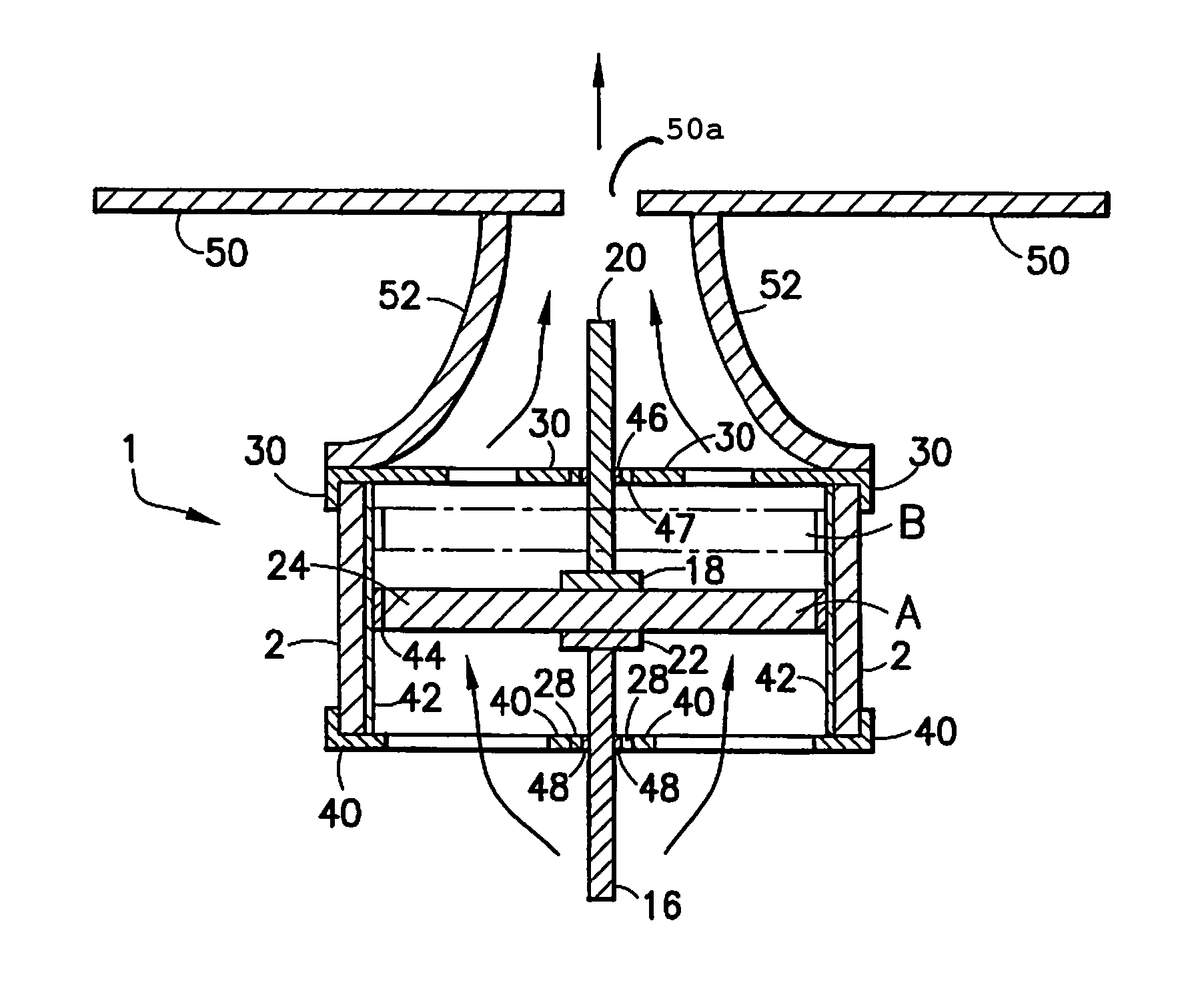
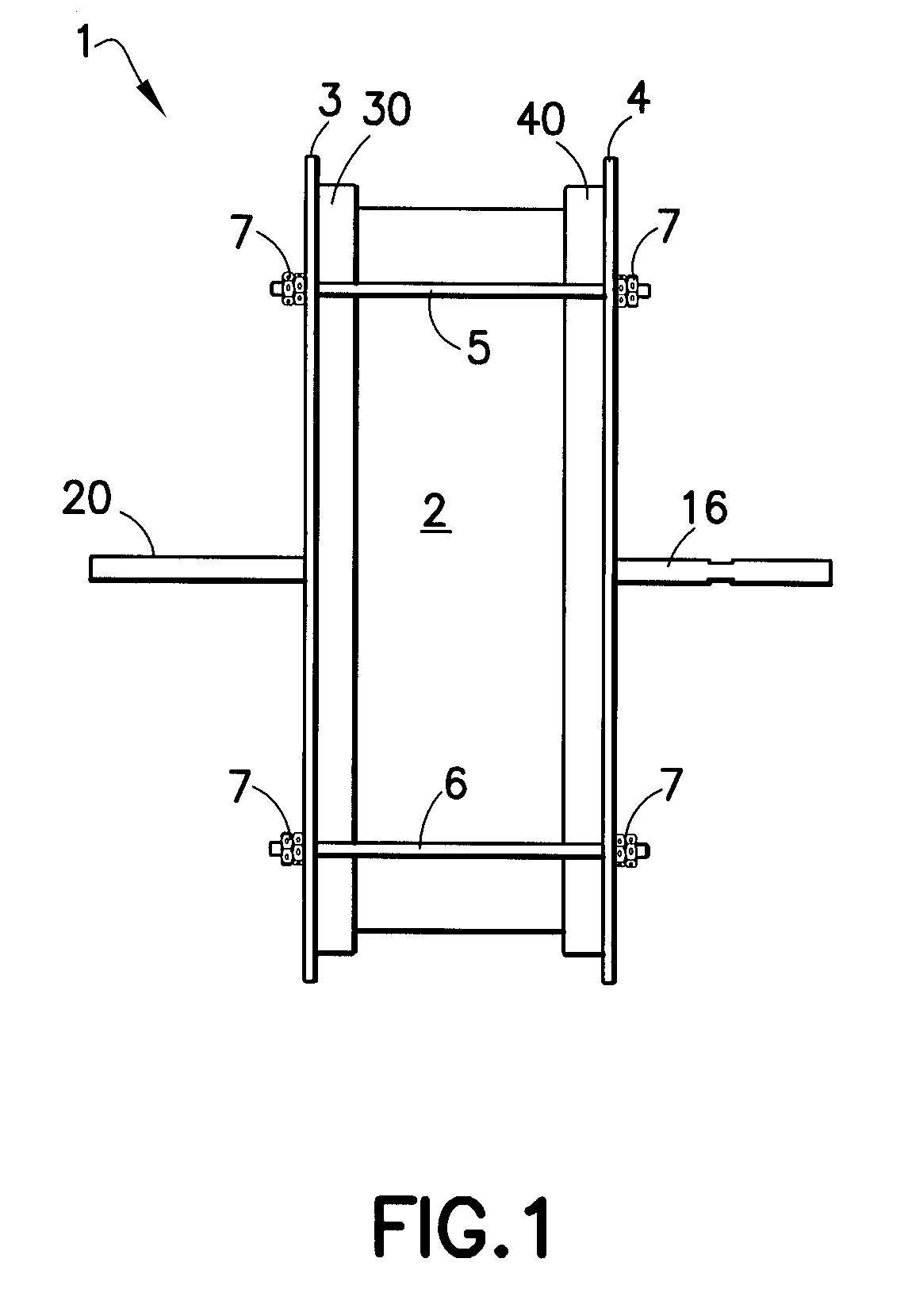
[0026]FIG. 1 depicts airfoil air pump assembly 1. The air pump assembly utilizes air pump housing 2 which has, respectively, rear housing cover 40 and front housing cover 30. The housing covers are held in place with rear cover ring 4 and front cover ring 3, the covers and cover rings are held securely in place on housing 2 with studs 5 and 6 which are fastened with jam nuts 7. Typically, four such studs will be sufficient. In this view, air pump shafts 16 and 20 are seen protruding from housing 2.

[0027]The air pump shown in FIG. 1 may be installed in proximity to and in communication with an aerodynamic surface. In one configuration, the air pump operates during travel by injecting a pulsed air flow into the air stream moving over the aerodynamic surface. The air pump operates at frequencies up to 300 hertz in a cyclic manner with reduced required energy input as a result of the use of an ultra-low friction amorphous carbon coating on frictional surfaces of key low inertia movable ...


PUM


Abstract

An air pump positioned within a hollow space in an aerodynamic structure for controlling the flow over an aerodynamic surface thereof, includes a movable member linearly displaced by a very low friction piston mechanism and a compression chamber open to the exterior of the aerodynamic surface through an orifice. Reciprocal displacement of the very low friction movable member changes the volume of the compression chamber to alternately expel fluid (e.g., air) from and pull fluid into the compression chamber through the orifice. The movable member includes a piston oscillating within a piston housing each having an ultra-low friction coating for improved thermal performance and reduced maintenance. Fluid intake to the compression chamber may be increased through the use of a one-way valve located either in the aerodynamic surface, or in the piston. Multiple flapper valves may surround the orifice in the aerodynamic surface for increased fluid control.

Description

FIELD OF THE INVENTION[0001]This invention relates generally to aerodynamic surfaces and, more particularly, to improved constructions for providing aerodynamic flow control.BACKGROUND OF THE INVENTION[0002]In general, the aerodynamic efficiency of any lifting surface, regardless of the type of vehicle, is dependent on the lift-to-drag ratio of that surface. Various methods for controlling aerodynamic surfaces on rotor blades, wings, engine inlets, fan blades, and nozzles are known. Movable control surfaces placed on these aerodynamic surfaces have included flaps, slats, spoilers, ailerons, elevators, and rudders. Although these control surfaces can mechanically alter the geometry of the original aerodynamic device, they are limited in their ability to respond quickly and efficiently. Furthermore, such mechanical control surfaces may have a number of disadvantages, including adding complexity to the aerodynamic device, reducing structural integrity, complicating manufacturing, and c...

Claims


Application Information

Patent Timeline
Patent Type & Authority Patents(United States)
IPC IPC(8): B64C3/00
CPCF04C21/002F04B39/0215F04B39/0292F04B9/107
Inventor BIRCHETTE, TERRENCE S.
Owner THE BOEING CO
Why Eureka
Try Eureka