Continuous feed chemical vapor deposition

a technology of chemical vapor deposition and continuous feed, which is applied in the direction of crystal growth process, polycrystalline material growth, chemically reactive gas growth, etc., to achieve the effect of preventing back diffusion

Active Publication Date: 2011-08-30
ALTA DEVICES INC
View PDF87 Cites 23 Cited by
  • Summary
  • Abstract
  • Description
  • Claims
  • Application Information

AI Technical Summary

Benefits of technology

[0023]In one embodiment, the CVD system is provided which includes an entrance isolator operable to prevent contaminants from entering the system at an entrance of the system, an exit isolator operable to prevent contaminants from entering the system at an exit of the system, and an intermediate isolator disposed between the entrance and exit isolators. The system may further include a first deposition zone disposed adjacent the entrance isolator and a second deposition zone disposed adjacent the exit isolator. The intermediate isolator is disposed between the deposition zones and is operable to prevent mixing of gases between the first deposition zone and the second deposition zone.
[0024]In one embodiment, the entrance isolator is further operable to prevent back diffusion of gases injected into the first deposition zone, the intermediate isolator is further operable to prevent back diffusion of gases injected into the second deposition zone, and the exit isolator is further operable to prevent back diffusion of gases injected into the second deposition zone. An isolation zone formed by at least one of the isolators has a length within a range from about 1 meter to about 2 meters. A gas, such as nitrogen, is injected into the entrance isolator at a first flow rate, such as about 30 liters per minute, to prevent back diffusion of gases from the first deposition zone. A gas, such as arsine, is injected into the intermediate isolator at a first flow rate, such as about 3 liters per minute, to prevent back mixing of gases between the first deposition zone and the second deposition zone. A gas, such as nitrogen, is injected into the exit isolator at a first flow rate, such as about 30 liters per minute, to prevent contaminants from entering the system at the exit of the system. In one embodiment, an exhaust is disposed adjacent each isolator and operable to exhaust gases injected by the isolators. An exhaust may be disposed adjacent each deposition zone and operable to exhaust gases injected into the deposition zones.
[0033]In one embodiment, a method for forming multiple epitaxial layers on a substrate using the CVD system is provided which includes introducing the substrate into a guide path, such as a channel, at an entrance of the system, while preventing contaminants from entering the system at the entrance, depositing a first epitaxial layer on the substrate, while the substrate moves along the channel of the system, depositing a second epitaxial layer on the substrate, while the substrate moves along the channel of the system, preventing mixing of gases between the first deposition step and the second deposition step, and retrieving the substrate from the channel at an exit of the system, while preventing contaminants from entering the system at the exit. The method may further include heating the substrate prior to depositing the first epitaxial layer, maintaining the temperature of the substrate as the first and second epitaxial layers are deposited on the substrate, and / or cooling the substrate after depositing the second epitaxial layer. The substrate may substantially float along the channel of the system. The first epitaxial layer may include aluminum arsenide and / or the second epitaxial layer may include gallium arsenide. In one embodiment, the substrate substantially floats along the channel of the system. The method may further include depositing a phosphorous gallium arsenide layer on the substrate and / or heating the substrate to a temperature within a range from about 300° C. to about 800° C. during the depositing of the epitaxial layers. A center temperature to an edge temperature of the substrate may be within 10° C. of each other.
[0035]In one embodiment, the CVD system is provided which includes an entrance isolator operable to prevent contaminants from entering the system at an entrance of the system, an exit isolator operable to prevent contaminants from entering the system at an exit of the system, and an intermediate isolator disposed between the entrance and exit isolators. The system may further include a first deposition zone disposed adjacent the entrance isolator and a second deposition zone disposed adjacent the exit isolator. The intermediate isolator is disposed between the deposition zones and is operable to prevent mixing of gases between the first deposition zone and the second deposition zone. A gas is injected into the entrance isolator at a first flow rate to prevent back diffusion of gases from the first deposition zone, a gas is injected into the intermediate isolator at a first flow rate to prevent back mixing of gases between the first deposition zone and the second deposition zone, and / or a gas is injected into the exit isolator at a first flow rate to prevent contaminants from entering the system at the exit of the system. An exhaust may be disposed adjacent each isolator and operable to exhaust gases injected by the isolators and / or disposed adjacent each deposition zone and operable to exhaust gases injected into the deposition zones.

Problems solved by technology

These distinct designs address a variety of challenges that are encountered during a CVD process, such as depletion effects, contamination issues, and reactor maintenance.

Method used


Image

  • Continuous feed chemical vapor deposition
  • Continuous feed chemical vapor deposition
  • Continuous feed chemical vapor deposition

Examples


Embodiment Construction

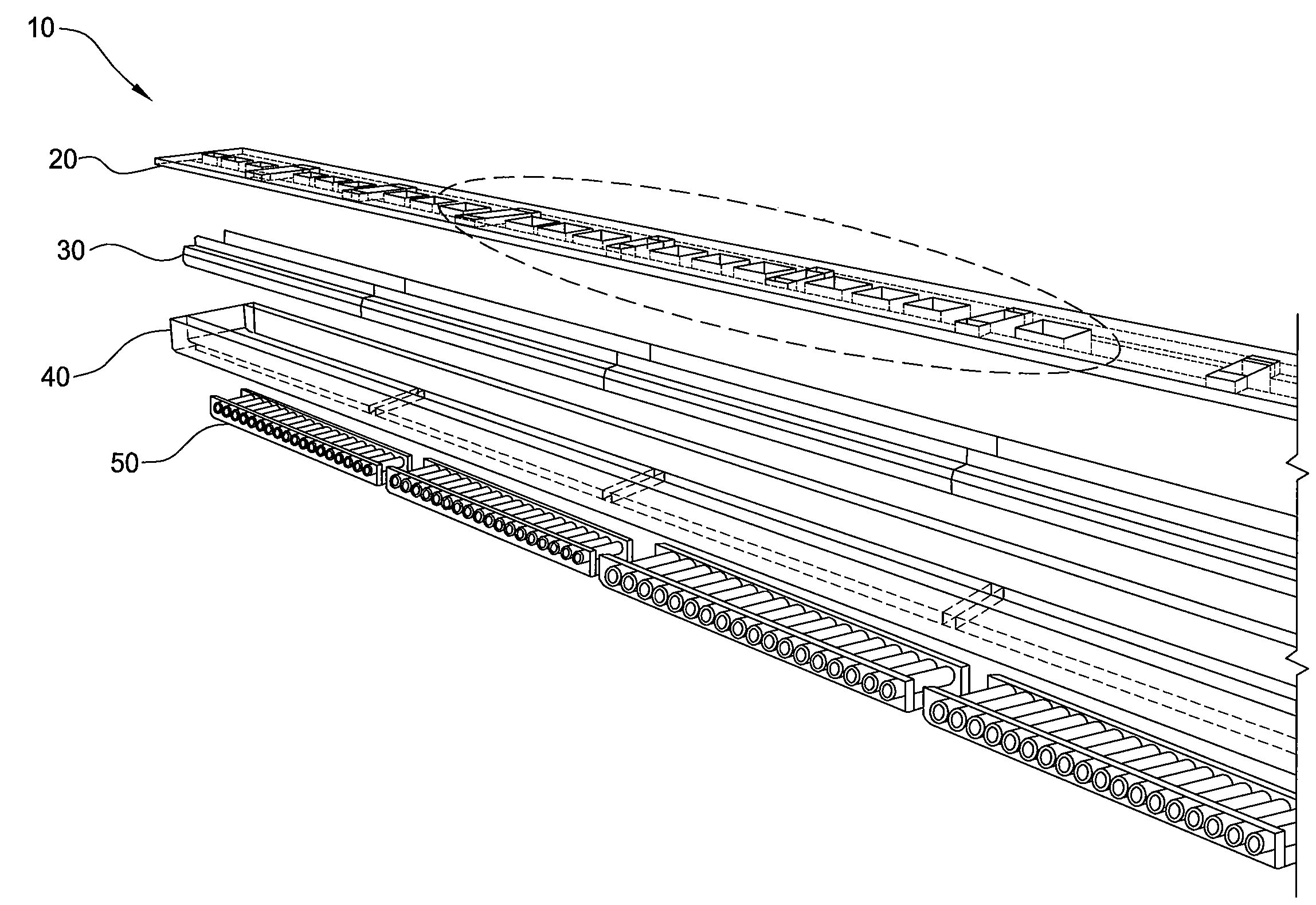
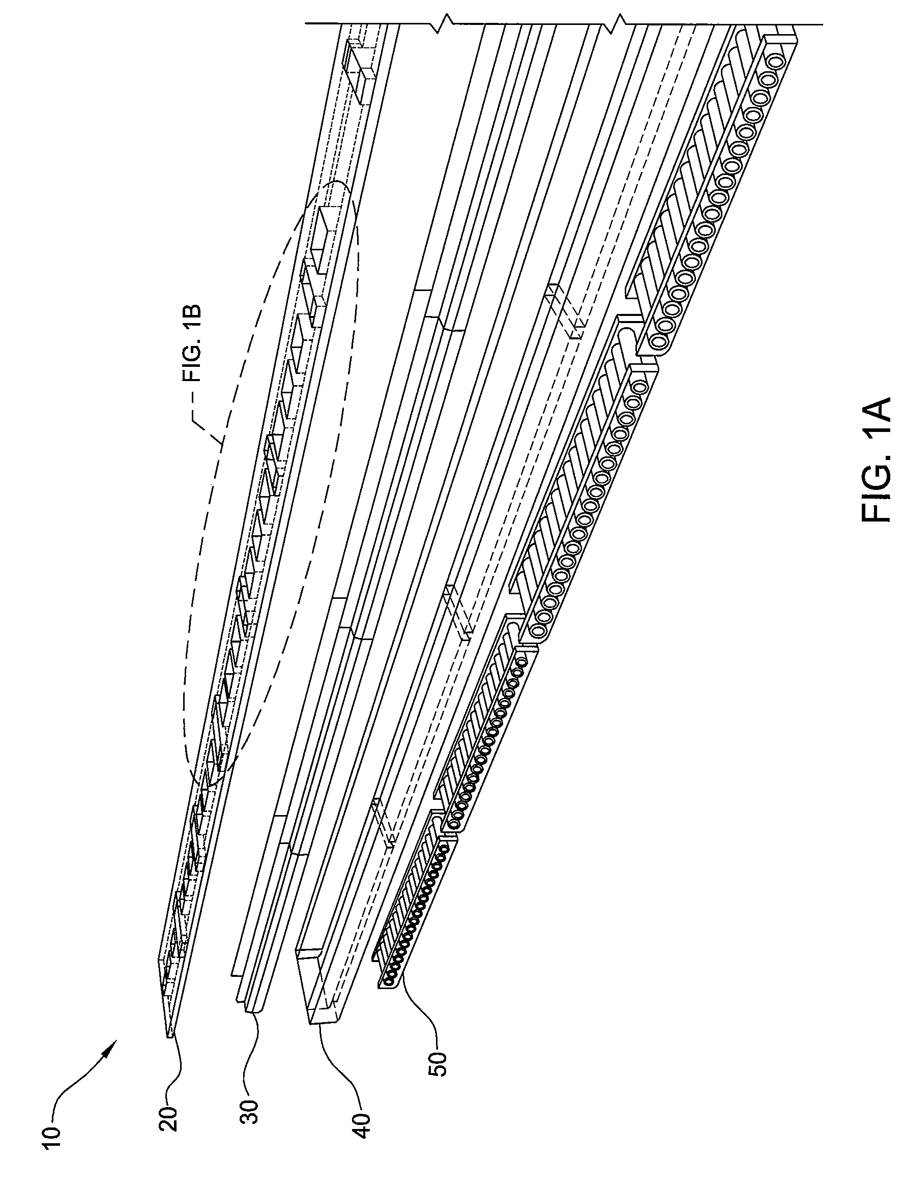
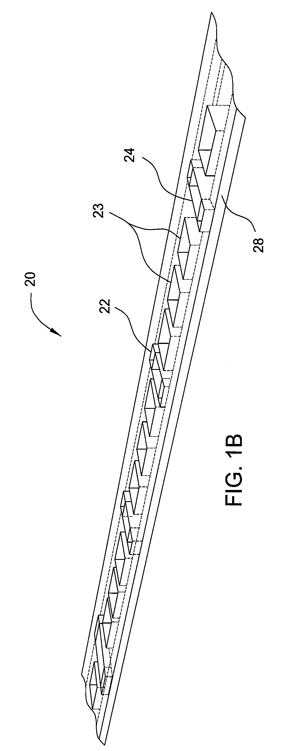
[0062]Embodiments of the invention generally relate to an apparatus and a method of chemical vapor deposition (“CVD”). As set forth herein, embodiments of the invention is described as they relate to an atmospheric pressure CVD reactor and metal-organic precursor gases. It is to be noted, however, that aspects of the invention are not limited to use with an atmospheric pressure CVD reactor or metal-organic precursor gases, but are applicable to other types of reactor systems and precursor gases. To better understand the novelty of the apparatus of the invention and the methods of use thereof, reference is hereafter made to the accompanying drawings.

[0063]According to one embodiment of the invention, an atmospheric pressure CVD reactor is provided. The CVD reactor may be used to provide multiple epitaxial layers on a substrate, such as a wafer, such as a gallium arsenide wafer. These epitaxial layers may include aluminum gallium arsenide, gallium arsenide, and phosphorous gallium ars...


PUM

PropertyMeasurementUnit
temperatureaaaaaaaaaa

Abstract

Embodiments of the invention generally relate to a method for forming a multi-layered material during a continuous chemical vapor deposition (CVD) process. In one embodiment, a method for forming a multi-layered material during a continuous CVD process is provided which includes continuously advancing a plurality of wafers through a deposition system having at least four deposition zones. Multiple layers of materials are deposited on each wafer, such that one layer is deposited at each deposition zone. The methods provide advancing each wafer through each deposition zone while depositing a first layer from the first deposition zone, a second layer from the second deposition zone, a third layer from the third deposition zone, and a fourth layer from the fourth deposition zone. Embodiments described herein may be utilized to form an assortment of materials on wafers or substrates, especially for forming Group III / V materials on GaAs wafers.

Description

CROSS-REFERENCE TO RELATED APPLICATIONS[0001]This application claims benefit of U.S. Ser. No. 61 / 104,288, filed Oct. 10, 2008, which is hereby incorporated by reference in its entirety.BACKGROUND OF THE INVENTION[0002]1. Field of the Invention[0003]Embodiments of the invention generally relate to methods and apparatuses for vapor deposition, and more particularly, to chemical vapor deposition processes and chambers.[0004]2. Description of the Related Art[0005]Chemical vapor deposition (“CVD”) is the deposition of a thin film on a substrate, such as a wafer, by the reaction of vapor phase chemicals. Chemical vapor deposition reactors are used to deposit thin films of various compositions on the substrate. CVD is highly utilized in many activities, such as during the fabrication of devices for semiconductor, solar, display, and other electronic applications.[0006]There are numerous types of CVD reactors for very different applications. For example, CVD reactors include atmospheric pre...

Claims


Application Information

Patent Timeline
Patent Type & Authority Patents(United States)
IPC IPC(8): H01L21/20H01L21/36C23C16/00
CPCC23C16/45519H01L21/67784C23C16/54C30B25/025H01L21/67173H01L21/6776C23C16/458H01L21/02463H01L21/02543H01L21/02546H01L21/0262C30B29/40C30B29/42H01L21/67109H01L21/67115H01L21/205
Inventor HE, GANGHIGASHI, GREGG
Owner ALTA DEVICES INC
Why Eureka
Try Eureka