Shield conductor and shield conductor manufacturing method

a manufacturing method and shielding technology, applied in the direction of power cables, rigid-tube cables, cables, etc., can solve the problems of increasing the number of parts, difficult to and easy confinement of heat generated in wires inside the pipe, so as to achieve cost reduction

Inactive Publication Date: 2011-09-06
AUTONETWORKS TECH LTD +2
View PDF21 Cites 19 Cited by
  • Summary
  • Abstract
  • Description
  • Claims
  • Application Information

AI Technical Summary

Benefits of technology

[0011]With the inner surface of the groove-like fitting member of the pipe attached tightly to the circumference of the wire, the heat generated in the wires is transmitted directly to the pipe, and then released to the air from the circumference of the pipe. The present invention excels in radiation performance, compared with the one constituted so that the greater part of the heat generated in wires is transmitted to the pipe through air layer.
[0045]According to the above configuration, the pipe can be formed from one metal plate material, and thereby achieving cost reduction.

Problems solved by technology

However, using a protector causes an increased number of parts.
In a shield conductor using a pipe, an air layer exists between wires and the pipe, and it is therefore difficult for heat generated in wires at the time of energizing to be transmitted to the pipe since the heat is cut off by air of low heat conductivity.
Moreover, since no venting pathway to the outside, like the clearance between knitted stitches in braided wires, exists in the pipe, heat generated in the wires is easily confined inside of the pipe.
Therefore, a shield conductor using a pipe tends to have a lower radiation performance.
Consequently, in an environment where the upper limit of the temperature rise value of the conductor is decided, and in a shield conductor of low radiation efficiency as mentioned above, it is necessary to restrain a heating value by enlarging the cross-section area of the conductor.
However, enlarging the cross-section area of a conductor means an increased diameter and weight of the shield conductor, and therefore requiring a countermeasure.
Therefore, it is difficult to externally fit the groove-like fitting member to the wire, as bending the wire so as to follow the crooked shape of the plate shaped composing member.
Then, hysteresis loss and eddy current loss increase, and thus, the metal generates heat.
Therefore, it now causes a problem of increased cost, since a non-magnetic substance needs to be used as a metal.

Method used


Image

  • Shield conductor and shield conductor manufacturing method
  • Shield conductor and shield conductor manufacturing method
  • Shield conductor and shield conductor manufacturing method

Examples


embodiment 1

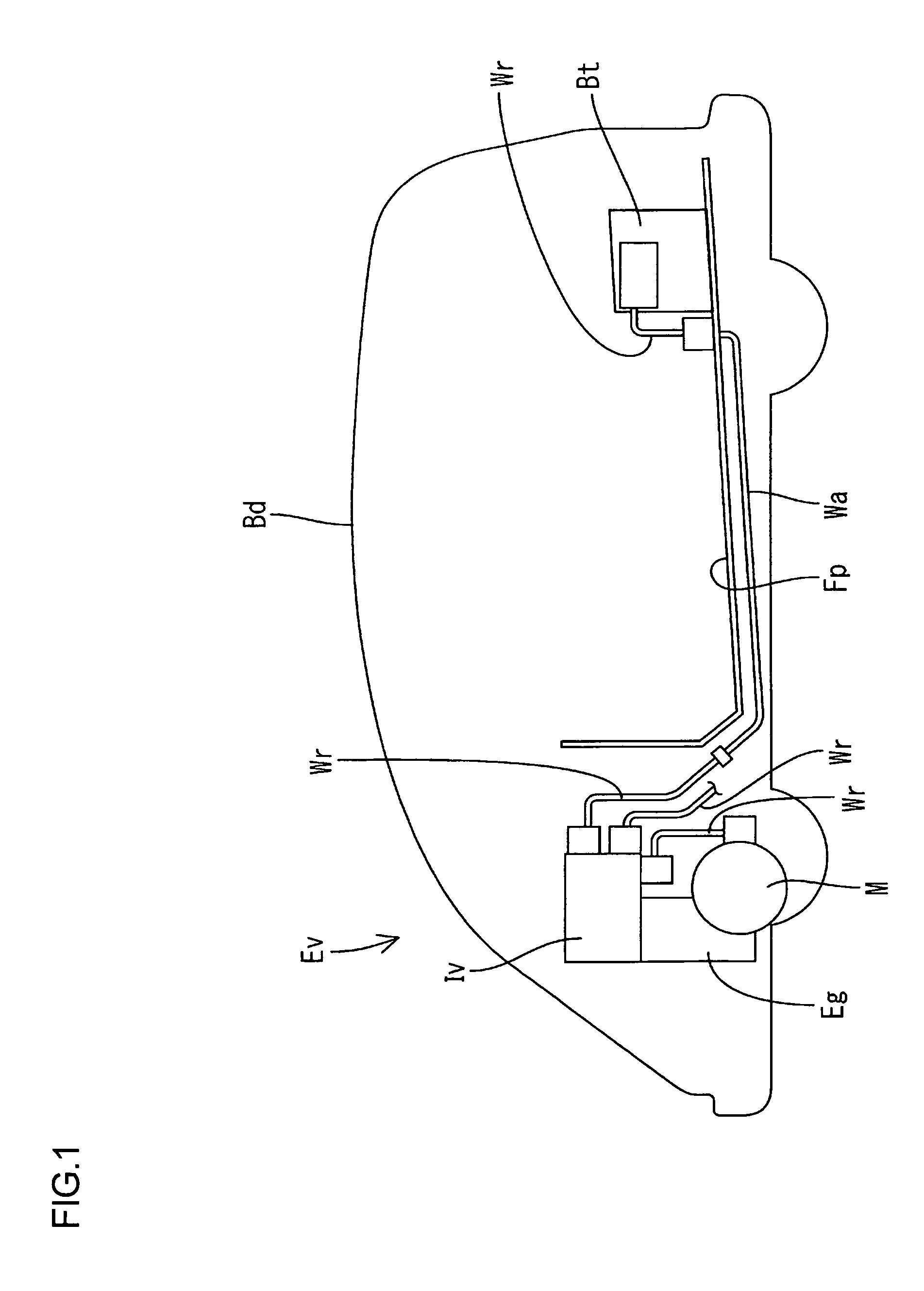
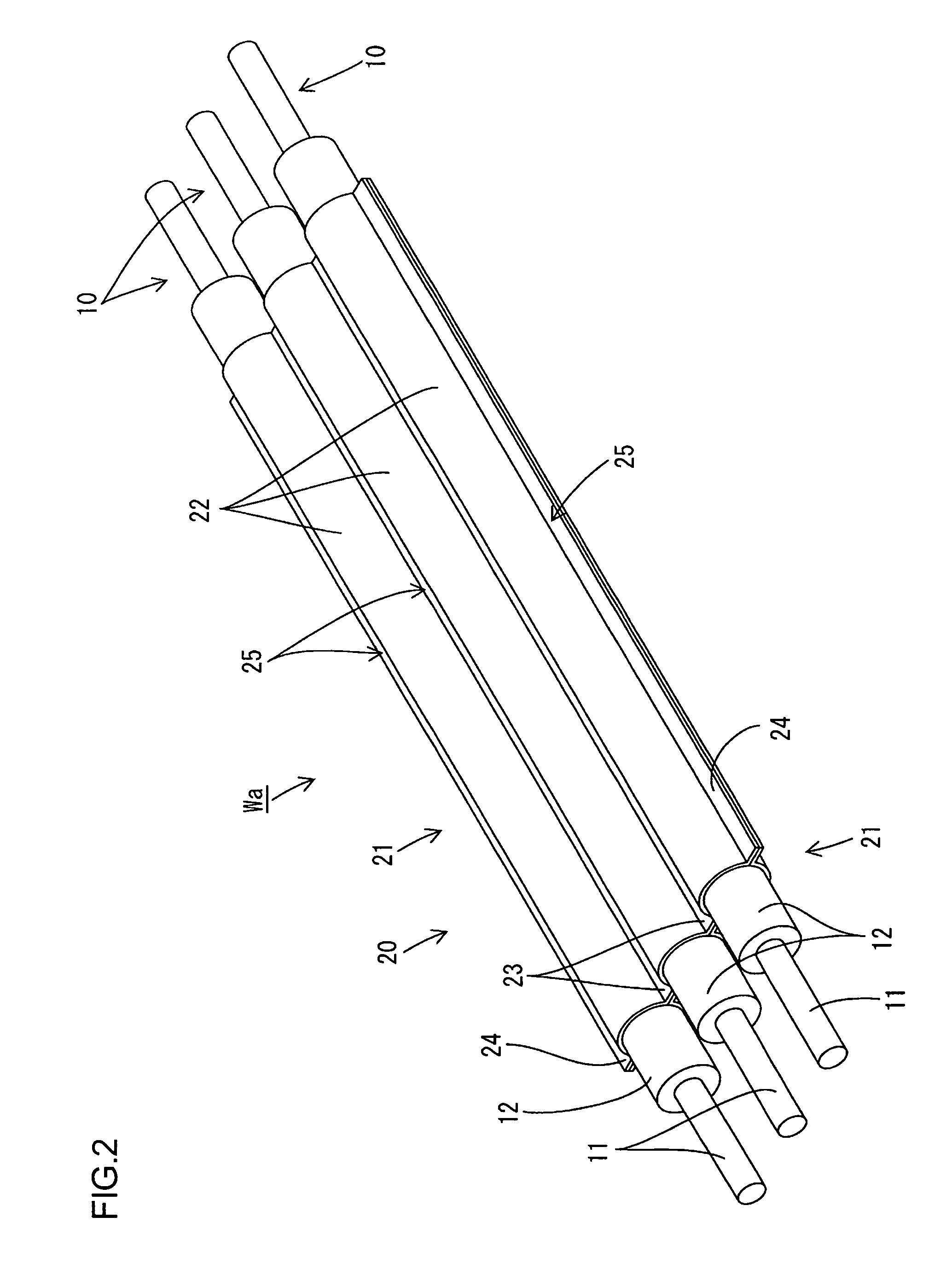
[0088]In what follows, as referring now to FIGS. 1 to 5, Embodiment 1 which materializes one aspect of the present invention, is described. A shield conductor Wa according to the present embodiment is, for example, placed between devices such as a battery Bt, an inverter Iv, and a motor M that compose a drive power source in an electric vehicle Ev (corresponding to a vehicle), and used for supplying an electric power for motive power. The shield conductor WA is constituted from a plurality of (three in the present embodiment) non-shielded wires 10 inserted into a pipe 20 having a collective shielding function as well as a wire protecting function. This shield conductor Wa is placed in the lower part of a floor plate Fp (under the floor) in a car body Bd of the electric vehicle Ev. The shield conductor Wa, the battery Bt, and the inverter Iv are connected through an in-car electrically-conducting path Wr. The gap between the inverter Iv and the motor M is also connected through the i...

embodiment 2

[0102]Next, as referring now to FIGS. 6 and 7, Embodiment 2 which materializes the present invention is described. In a shield conductor Wb according to the present Embodiment 2, the shape of a pipe 40 and the arrangement of the wire 10 inside of the pipe 40 are constituted differently from those in the above Embodiment 1. Since the other structures are the same as those in Embodiment 1, the same reference numbers are allotted to those of the corresponding structures, omitting descriptions on constitution, working, and effect.

[0103]The three wires 10 are arranged in positions attached tightly to each other, with their axis lines forming a right equilateral triangle. The pipe 40 is constituted by cylindrically combining three, press-molded plate shaped composing members 41. Three plate shaped composing members 41 may be formed from a non-magnetic substance (such as Cu, Bs, and Al, or an alloy made from theses metals, or SUS), or from a magnetic substance (such as iron plate or steel ...

embodiment 3

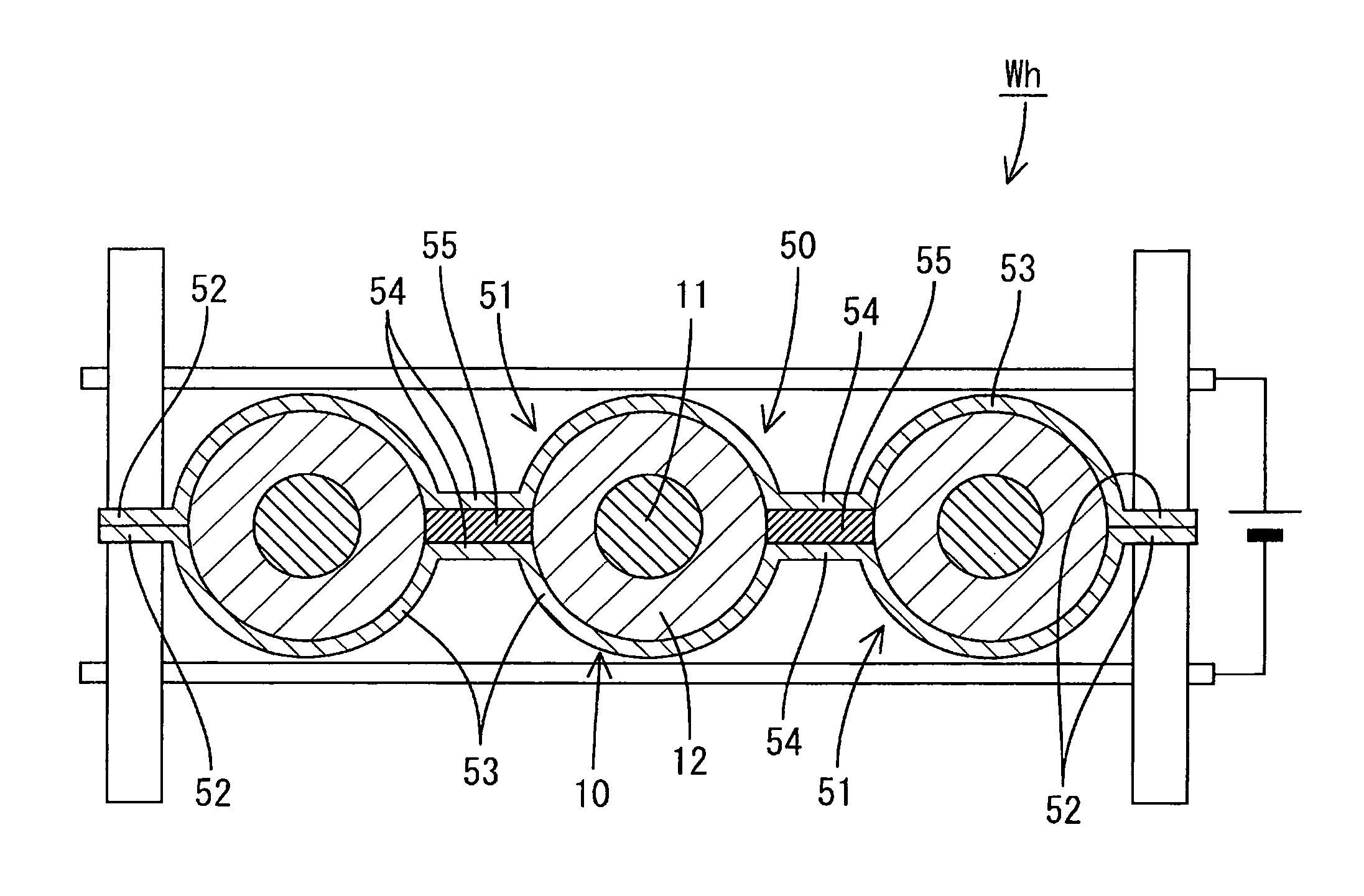
[0107]Next, as referring now to FIG. 8, Embodiment 3 which materializes the present invention is described. In a shield conductor Wc according to the present Embodiment 3, the shape of a pipe 50 is constituted differently from that in the above Embodiment 1. Since the other structures are the same as those in Embodiment 1, the same reference numbers are allotted to those of the corresponding structures, omitting descriptions on constitution, working, and effect. The pipe 50 is constituted by combining a pair of vertically symmetrical plate shaped composing members 51, while two ears (corresponding to an abutting member) 52 and three groove-like fitting members 53 are formed in each plate shaped composing member 51. With three wires 10 held between the combined plate shaped composing members 51, the ears 52 are tightly attached each other so that this tightly attached part is rigidly and conductibly fixed by welding, however, the corresponding upper and lower connecting parts 54 each...


PUM

PropertyMeasurementUnit
circumferenceaaaaaaaaaa
electric poweraaaaaaaaaa
shapeaaaaaaaaaa

Abstract

A shield conductor Wa comprises: a metallic pipe 20, a wire 10 to be inserted into the pipe 20, and a groove-like fitting member 22 provided in the pipe 20 as extending along the direction of axis of the wire 10, and at the same time, attached tightly to the circumference of the wire. With the inner surface of the groove-like fitting member 22 in the pipe 20 attached tightly to the circumference of the wire 10, the heat generated in the wire 10 is transmitted directly to the pipe 20, and then released to the air from the circumference of the pipe 20. This improves radiation performance of the shield conductor Wa.

Description

TECHNICAL FIELD[0001]The present invention relates to a shield conductor and a shield conductor manufacturing method.BACKGROUND ART[0002]As a shield conductor using a non-shielded wire, there has been one collectively shielding a plurality of non-shielded wires by enwrapping with a shielding member composed of a tubular braided wire made of metal thin wires woven into meshes. As a protecting method for shielding members and wires in this kind of shield conductor, means for enwrapping shielding members with a protector made from synthetic resin has been generally known. However, using a protector causes an increased number of parts.[0003]Considering the foregoing, the applicant of the present application has suggested, as described in Patent Literature 1, a structure wherein a non-shielded wire is inserted into a metal pipe. According to this configuration, the pipe fulfills functions of shielding and protecting wires, and it is therefore advantageous that the configuration requires ...

Claims


Application Information

Patent Timeline
Patent Type & Authority Patents(United States)
IPC IPC(8): H01R9/05
CPCH01B7/16H01B7/17H01B7/426Y10T29/49117H01B13/2633
Inventor WATANABE, KUNIHIKOMIYAKI, HIDEOIZAWA, KATSUTOSHI
Owner AUTONETWORKS TECH LTD
Why Eureka
Try Eureka