Optical transceiver with equalizing function and a method to setup the optical transceiver

a technology of optical transceivers and equalizing functions, which is applied in the field of optical transceivers, can solve the problems of large dynamic range of pre-compensation, hard thermal condition of the devices installed within the transceiver, and the inability of multi-mode fibers to transmit high-speed optical signals, and achieve the effect of dynamic range of equalization

Active Publication Date: 2011-10-18
SUMITOMO ELECTRIC IND LTD
View PDF3 Cites 23 Cited by
  • Summary
  • Abstract
  • Description
  • Claims
  • Application Information

AI Technical Summary

Benefits of technology

[0011]Thus, the present invention is to solve the subjects above, to provide an optical transceiver that is able to compensate the distortion and the dispersion appeared in the high speed transmission due to the electrical signal lines, the semiconductor active devices, and the optical fiber, and to provide a method to setup the optical transceiver.
[0012]One aspect of the present invention relates to an optical transceiver that comprises a transmitter and a receiver. The transmitter includes an LD for emitting a transmitted optical signal to a first optical fiber and a first equalizer unit for outputting a first electrical signal equalized from a transmitted electrical signal input to the transmitter. The receiver includes a PD for converting a received optical signal provided from a second optical fiber to a second electrical signal, and a second equalizer unit that outputs a received electrical signal equalized from the second electrical signal output from the PD to an outside of the transceiver. A feature of the transceiver according to the present invention is that the first equalizer unit in the transmitter compensates the frequency distortion contained in the first electrical signal output from the first equalizer unit, the frequency distortion contained in the second electrical signal output from the PD and the frequency distortion due to the LD and the PD, while, the second equalizer unit in the receiver compensates the dispersion of the second optical fiber coupled with the receiver.
[0013]Because the transceiver provides the first equalizer unit that compensates only the distortion due to the limited bandwidth of the electrical signal lines and that of the active devices, namely, the LD and the PD, independent of the second equalizer unit in the receiver, the dynamic range of the equalizing for the dispersion of the optical fiber, which is performed solely by the second equalizer unit, may be enhanced.

Problems solved by technology

Thus, it has been unable for the multimode fiber to transmit a high speed optical signal.
Moreover, the pre-compensation technique reported by Roberts, et. al is necessary to compensate whole distortion and dispersion due to the signal line, the active devices and the optical fiber only by the pre-compensation, which inevitably requires a large dynamic range of the pre-compensation.
A large power is necessary in the calculation to get optimal conditions, which inevitably brings a hard thermal condition for the devices installed within the transceiver.

Method used


Image

  • Optical transceiver with equalizing function and a method to setup the optical transceiver
  • Optical transceiver with equalizing function and a method to setup the optical transceiver
  • Optical transceiver with equalizing function and a method to setup the optical transceiver

Examples


first embodiment

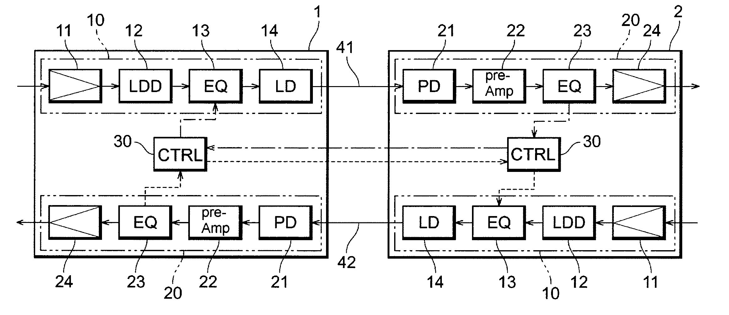
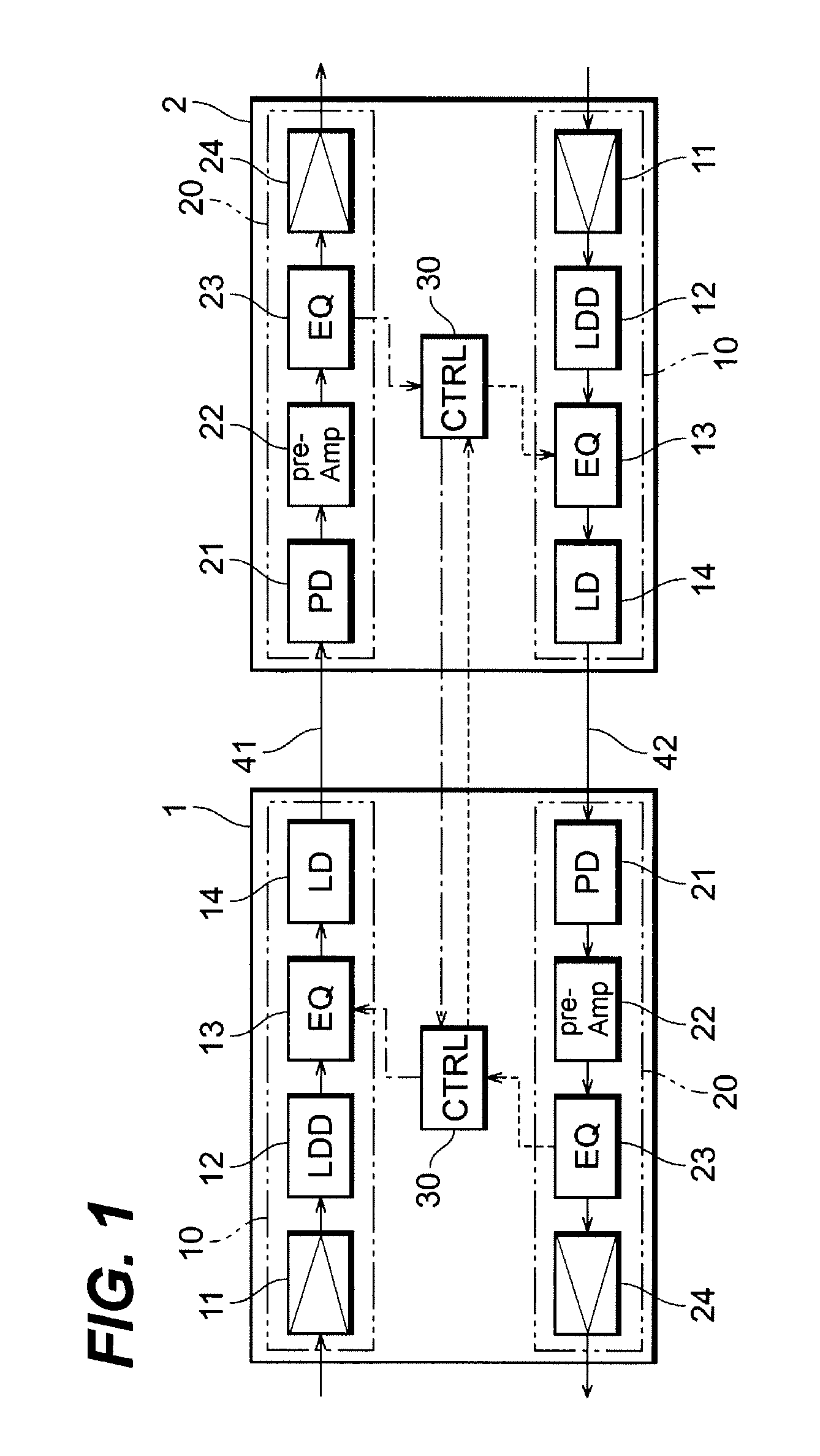
[0023]The first embodiment of the invention will be described. FIG. 1 illustrates a configuration of an optical transceiver according to the first embodiment of the invention and a method to setup the transceiver. FIG. 1 includes first and second transceivers, 1 and 2, each having the same configuration with respect to the other. That is, the optical transceiver, 1 and 2, include a transmitter 10, a receiver 20 and a control unit (CTRL) 30.

[0024]The transmitter 10 comprises a reshaping unit 11, a laser diode driver unit (hereafter denoted as LDD unit) 12, an equalizer unit (hereafter denoted as EQ unit) 13 for the transmitting signal, and a laser diode (hereafter denoted as LD) 14. The reshaping unit 11, by receiving an input signal, reshapes its waveform and transmits the reshaped signal to the LDD 12. The LDD 12 generates a driving signal to drive the LD 14 based on the reshaped signal from the reshaping unit 11. The EQ unit 13 equalizes the signal from the LDD 12 and transmits th...

second embodiment

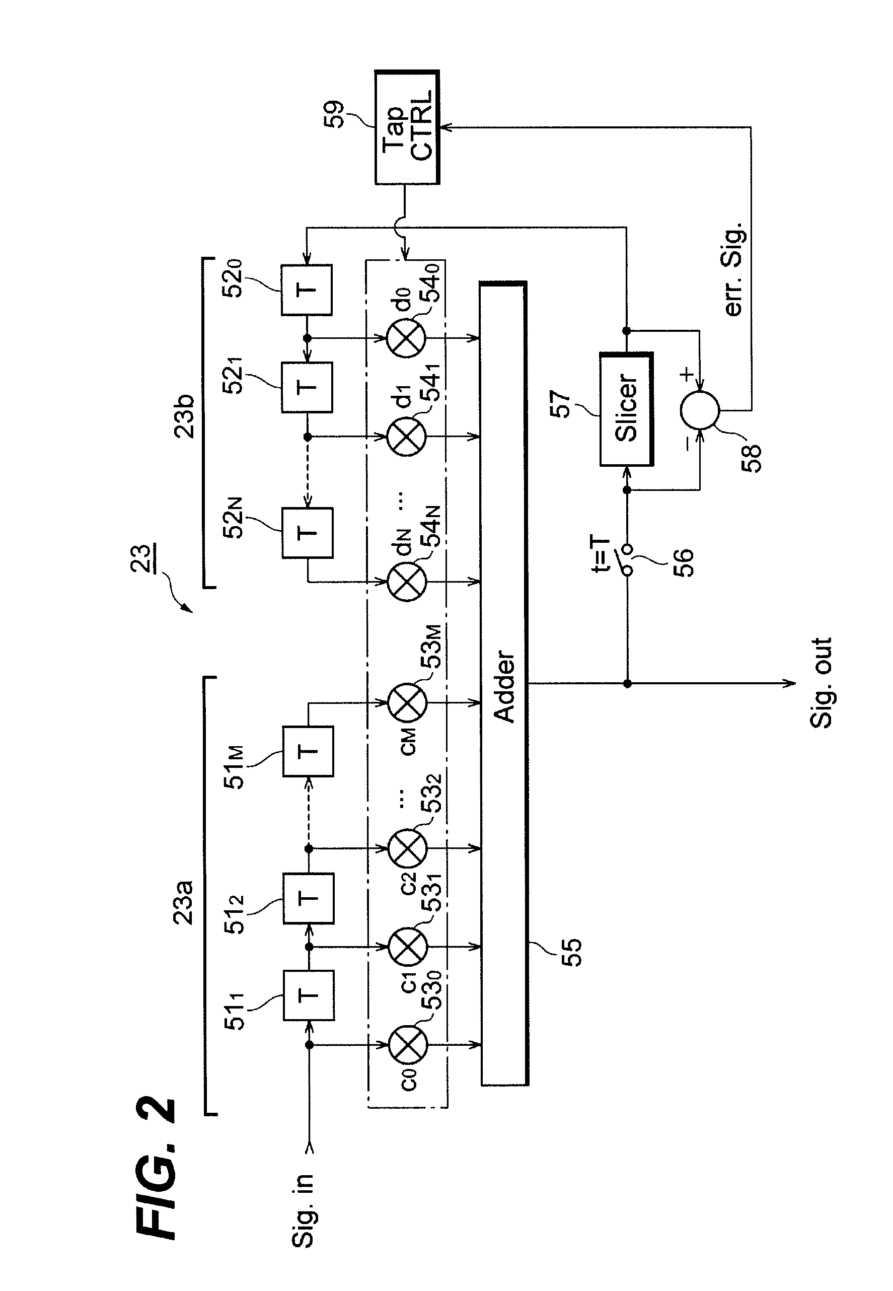
[0046]Next, a second embodiment according to the invention will be described. FIG. 4 illustrates only one transceiver 3, which has the same configuration with the transceivers, 1 and 2, they are already described above, and respective units, 11 to 14 and 21 to 24, in the transceiver 3 are also same as those in the previous transceivers, 1 and 2. A feature of the transceiver 3 is that the controller 30 sets the tap coefficients of the EQ unit 23 in the receiver 20 and, based on these tap coefficients thus decided, the controller 30 sets the tap coefficients of the EQ unit 13 in the transmitter 10.

[0047]As shown in FIG. 4, the transceiver 3 firstly couples the transmitter 10 with its own receiver 20 by an optical fiber 43 with substantially no dispersion. Further, as described in the first embodiment, only one of the tap coefficients, c0 to cM, of the EQ unit 13 is set equal to 1, while, the other in the feed forward unit 13a are set to 0, and all tap coefficients, d0 to dN, in the fe...


PUM


Abstract

An optical transceiver and a method to setup the optical transceiver are disclosed, where the transceiver has a function to compensate the distortion and the dispersion due to the limited bandwidth of the electrical signal line, that of the active devices, and that of the optical fiber. The optical transceiver comprises a transmitter with an equalizer unit and a receiver also with an equalizer unit. The equalizer unit in the transmitter compensates the distortion due to the limited bandwidth of the transmission lines for the electrical signal and that of the semiconductor active device, while, the equalizer unit in the receiver compensates the dispersion due to the limited bandwidth of the optical fiber.

Description

BACKGROUND OF THE INVENTION[0001]1. Field of the Invention[0002]The present invention relates to an optical transceiver that transmits and receives optical signals.[0003]2. Related Prior Arts[0004]One optical communication system, whose distance between the nearest terminal is shorter than several kilo-meter and transmission speed is relatively slow, below several hundreds of mega-bps, often uses multimode optical fibers and a light-emitting diode (LED) as optical sources. On the other hand, another type of the optical communication system with a long distance and a high transmission speed uses single mode fibers and a laser diode as optical sources.[0005]The FDDI standard, which is one of international standards of the optical communication and rules a distance of 2 km and a transmission speed of 125 Mbps, has adopted the multimode fiber with a core diameter of 62.5 μm and a graded index profile. Another standard of the optical communication system, such as the SDH (Synchronous Dig...

Claims


Application Information

Patent Timeline
Patent Type & Authority Patents(United States)
IPC IPC(8): H04B10/00H03H17/00H03H17/04H04B3/04H04B3/06H04B10/07H04B10/2507H04B10/2513H04B10/40H04B10/43H04B10/50H04B10/60H04B10/69
CPCH04B10/25133H04B10/40
Inventor KATO, TAKATOSHI
Owner SUMITOMO ELECTRIC IND LTD
Why Eureka
Try Eureka