Electric vehicle having multiple-use APU system

a technology of electric vehicles and auxiliary power units, which is applied in the direction of propulsion parts, gas pressure propulsion mounting, machines/engines, etc., can solve the problems of high cost, high speed, and long trip patterns of driving, and the battery technology is the limiting factor in terms of cost, functionality (range), and durability of ev systems. , to achieve the effect of reducing the net metered electricity, high power and low impedan

Active Publication Date: 2011-10-25
APTIV TECH LTD
View PDF14 Cites 20 Cited by
  • Summary
  • Abstract
  • Description
  • Claims
  • Application Information

AI Technical Summary

Benefits of technology

[0019]Briefly described, during periods of vehicle inactivity, a vehicle-based APU electric generating system may be coupled into a regional electric grid through a grid outlet at a docking facility, such as residence, place of business, or truck stop, either independently of the vehicle of through the vehicle's battery, and may be thus operated to send electricity into the grid, reducing the net metered electricity for that outlet. A currently-preferred APU is a solid oxide fuel cell system. Preferably, the vehicle's battery has high power and low impedance, such as is a characteristic of lithium ion (LI) batteries, which is very attractive for rapid, shallow charging and discharging cycles. When a large number of vehicles are thus equipped and connected, a very substantial electric buffering can be effected to the grid load, thus reducing the need for excess grid capacity wherein fossil-fueled generating stations are kept spinning at essentially no load (known in the art as “spinning losses”) so that they can respond immediately to second-by-second fluctuations in electricity demand. The high efficiency of an SOFC at light load and the potential to use high-quality waste heat for building HVAC functions make the effective “spinning loss” of a hot, standby SOFC APU very low when compared to the spinning loss of central power stations. Through a communications network and control system, the SOFCs from some vehicles can be automatically on grid-standby and selectively commissioned to supply the regional grid with electricity, based on being still hot from a recent vehicle drive cycle, whereas the SOFCs in other vehicles, connected to the grid but powered down, can be started up automatically on short notice by the network and control system to supplement the grid during expected seasonal and diurnal peaks in grid demand.
[0021]Additionally, a docking facility such as a residence, business or truck stop may be supplied via a storage tank or supply system with hydrocarbon fuel, either in liquid form such as gasoline, kerosene, or diesel, or a gaseous hydrocarbon such as methane, ethane, propane, butane, isobutane, natural gas, and combinations thereof. Gaseous hydrocarbon is readily supplied by pipe in many locations as a commercial and residential heating fuel. The hydrocarbon reformer on board the vehicle can be attached directly to the fuel source via a metering valve, enabling an SOFC to operate as a stand-alone stationary power source indefinitely. In addition to connecting the vehicle-based APU to such a hydrocarbon source, an optional gas fuel storage tank on board the vehicle may be refueled with gaseous fuel, for example, while the battery is being electrically recharged by the grid outlet.

Problems solved by technology

A key issue for future mass viability is whether technical maturity and higher volume production can meet the market-demanded price level.
They are not well suited to higher mileage, higher speed, and longer trip patterns of driving in the USA, nor to operation in cold weather; however, land use, climate, and population density in many parts of the world are well-suited to EV use.
However, battery technology has been and continues to be the limiting factor in terms of cost, functionality (range), and durability of EV systems.
Battery systems required to provide purely electric vehicles with a reasonable range and speed are still excessively bulky and costly.
A disadvantage of any ICE hybrid system, however, is the level of combustion emissions characteristic of an ICE, requiring expensive and complex emission controls.
Despite advances in emissions control technology, an ICE still produces gaseous emissions, including some level of carbon monoxide, and cannot be operated safely for extended periods in a structure with limited ventilation such as a closed garage.
Another disadvantage of an ICE hybrid system is its relatively low efficiency in terms of fuel-to-electric conversion and fuel-to-thermal conversion.
This lowers the efficiency of the vehicle when the ICE is running, especially in cold weather conditions.
This requires a fuel cell of 50-100 kW peak power for a typical car or light truck and places severe demands on fuel cell start-up and transient response.
Such a large fuel cell is clearly a substantial cost challenge using present-day technology.
A serious problem in the art is that PEM fuel cells are intolerant of CO in the hydrogen fuel stream, such as is generated by a typical hydrocarbon catalytic reformer.
Thus, generating hydrogen onboard by reforming hydrocarbons requires a large, complex, multistage reformer and gas cleanup system to make the H2 of sufficient purity to run the PEM fuel cell.
Further, the cost, size, transient response, and start-up time realities of such a PEM reformer make a buffer of stored H2 essential, adding further cost and complexity.
For these reasons, a PEM hybrid vehicle is ill-suited for range-extended operation by reforming hydrocarbons onboard.

Method used


Image

  • Electric vehicle having multiple-use APU system
  • Electric vehicle having multiple-use APU system

Examples


Embodiment Construction

[0025]The invention covers strategies for non-vehicular uses of a plugged-in hybrid vehicle having an onboard rechargeable electrical energy source, such as a battery, and an onboard APU, preferably an SOFC system.

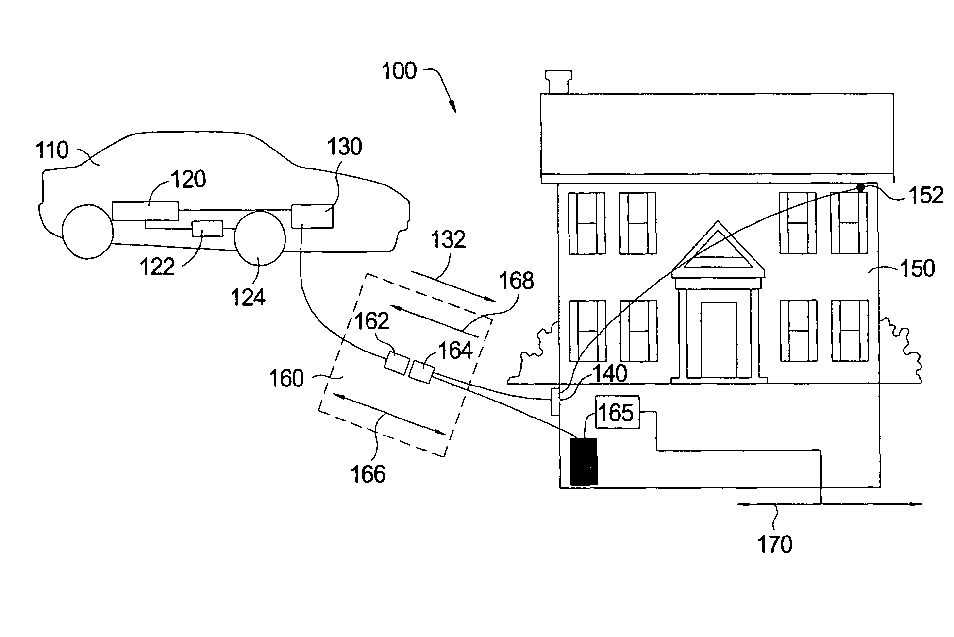
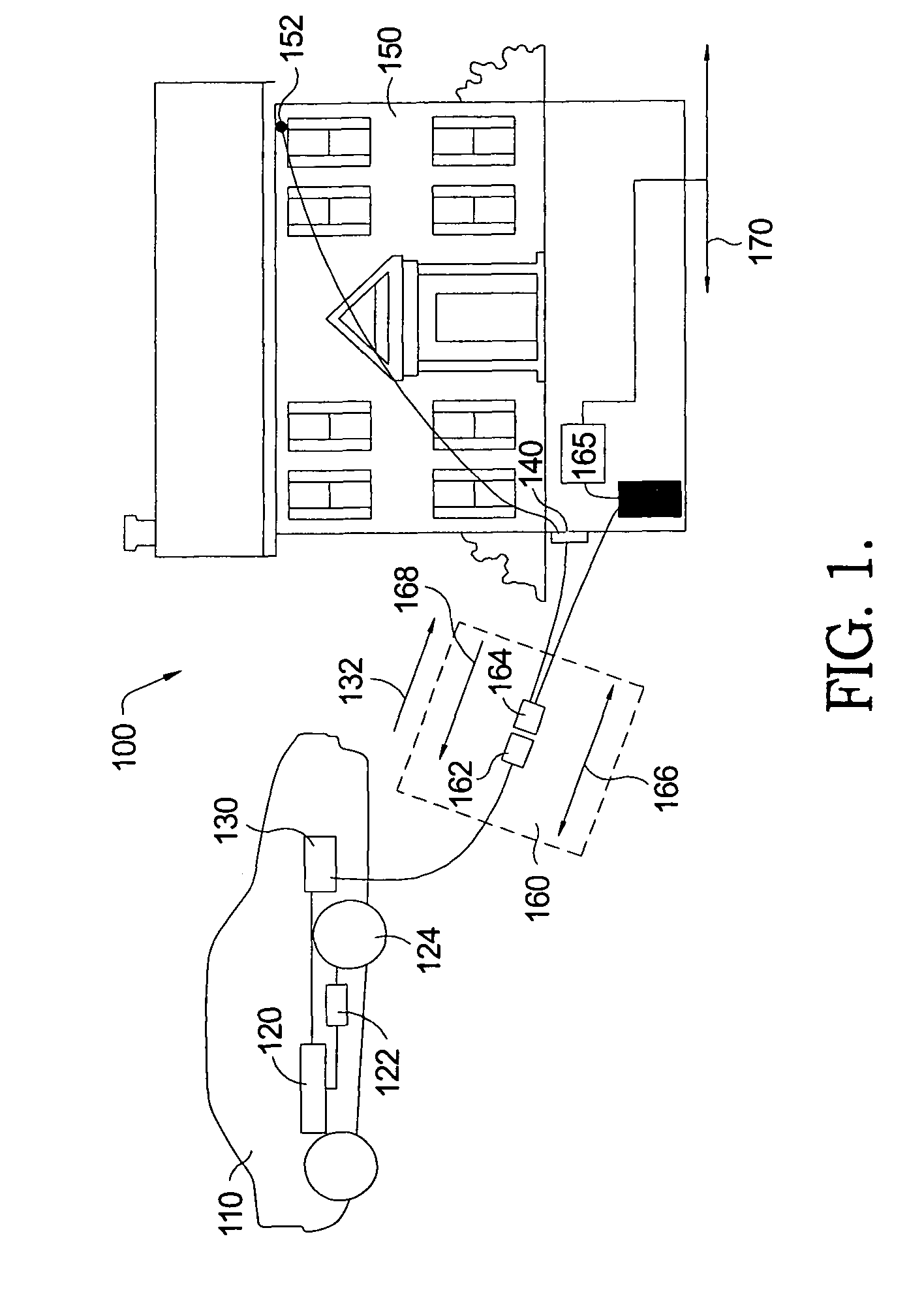
[0026]Referring to FIG. 1, a first embodiment 100, includes a hybrid electric vehicle 110 and stationary structure 150, for example, a residence, office, shopping center, truck stop, parking lot docking station, or other structure, electrically connected to a regional grid 152. Vehicle 110 includes one or more batteries 120, preferably low-impedance batteries such as nickel metal hydride or lithium ion batteries, as its primary source of energy for powering an electric motor 122 connected to wheel 124 for vehicle propulsion. Batteries 120 may be recharged by being plugged into an outlet 140 of structure 150 connected to regional grid 152 when the vehicle is stationary or by APU 130 (preferably an SOFC or optionally by an onboard ICE / generator or PEM) for recharging the bat...


PUM


Abstract

During periods of vehicle inactivity, a vehicle-based APU electric generating system may be coupled into a regional electric grid to send electricity into the grid. A currently-preferred APU is a solid oxide fuel cell system. When a large number of vehicles are thus equipped and connected, substantial electric buffering can be effected to the grid load. A vehicle-based APU can also function as a back-up generator to a docking facility in the event of power failure of the grid. Gaseous hydrocarbon is readily supplied by pipe in many locations as a commercial and residential heating fuel source, and a hydrocarbon reformer on the vehicle can be attached to the fuel source, enabling an APU to operate as a stationary power source indefinitely. An optional storage tank on the vehicle may be refueled with gaseous fuel, for example, while the battery is being electrically recharged by the grid.

Description

RELATIONSHIP TO OTHER APPLICATIONS AND PATENTS[0001]The present application claims priority from U.S. Provisional Patent Application, Ser. No. 60 / 668,166, filed Apr. 4, 2005.TECHNICAL FIELD[0002]The present invention relates to electric-powered vehicles (EVs); more particularly, to EVs having auxiliary power units (APUs) for recharging batteries in the EVs; and most particularly, to an electric vehicle having an electric battery and a solid oxide fuel cell APU wherein the fuel cell may be used for recharging the battery and also for non-vehicular uses, including supplementing a regional grid with electric power when the vehicle is not in use.BACKGROUND OF THE INVENTION[0003]Specialty electric vehicles (EVs) of various types are well known for indoor applications (for example, forklifts, wheelchairs, and airport people-movers for the elderly) and for short-trip outdoor use (golf carts, neighborhood electric vehicles, and handicapped scooters). Such vehicles typically are purely elect...

Claims


Application Information

Patent Timeline
Patent Type & Authority Patents(United States)
IPC IPC(8): B60L11/18H02J7/00
CPCB60L11/18B60L11/1816B60L11/1842B60L11/1887B60K1/04H02J3/387Y02E60/721Y02T90/121Y02T90/128Y02T90/14Y02T90/163Y02T90/34Y04S10/126H02J2001/004Y02T10/7072B60L50/50B60L53/14B60L55/00B60L58/40H02J2300/30H02J2300/10H02J3/381Y02E60/00Y02T10/70Y02T90/12Y02T90/16Y02T90/40
Inventor GRIEVE, MALCOLM JAMESMACBAIN, JOHN A.BOTTI, JEAN J.
Owner APTIV TECH LTD
Why Eureka
Try Eureka