Multi-stage cavitation device

a cavitation device and multi-stage technology, applied in the direction of mechanical equipment, transportation and packaging, hydrocarbon oil cracking process, etc., can solve the problems of cavitation bubble formation, achieve the effect of improving the efficiency and productivity of treatment, enhancing the efficiency of process, and reducing equipment, handling and energy costs

Active Publication Date: 2011-10-25
CAVITATION TECH
View PDF31 Cites 56 Cited by
  • Summary
  • Abstract
  • Description
  • Claims
  • Application Information

AI Technical Summary

Benefits of technology

[0026]The present invention creates beneficial conditions that cannot be duplicated, because the process's efficiency is enhanced by multiple, consecutive applications of high pressure, elevated heat, turbulence and vigorous mixing, applied in a flow-through manner within a short period. The preferred embodiments of the present invention apply optimized levels of both pressure and temperature via a controlled flow-through hydrodynamic cavitation. The process is independent of external temperatures and pressure and provides a means of changing chemical composition, physical properties and other characteristics of fluids evenly throughout the flow. In addition, important economic benefits are experienced through implementing the present invention. The optimized usage of a flow-through hydrodynamic multi-stage cavitation reactor serves to lower equipment, handling and energy costs, as it improves efficiency and productivity of the treatment.

Problems solved by technology

The fluidic mixture is then exposed to cavitation inducing features in each of the cavitation zones, which results in the formation of cavitation bubbles.

Method used


Image

  • Multi-stage cavitation device
  • Multi-stage cavitation device
  • Multi-stage cavitation device

Examples


example 1

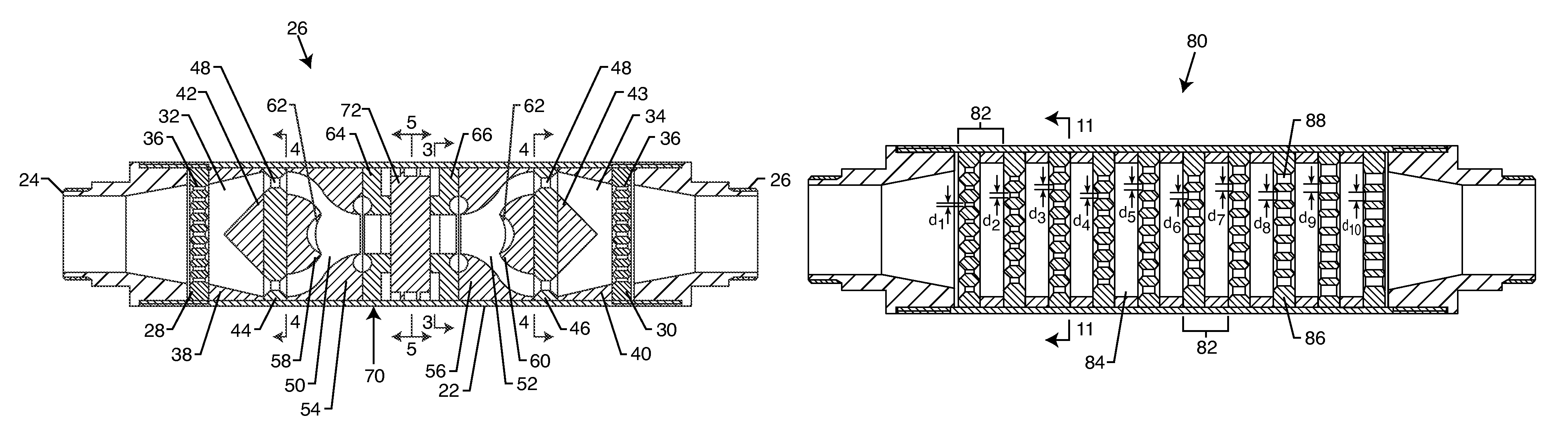
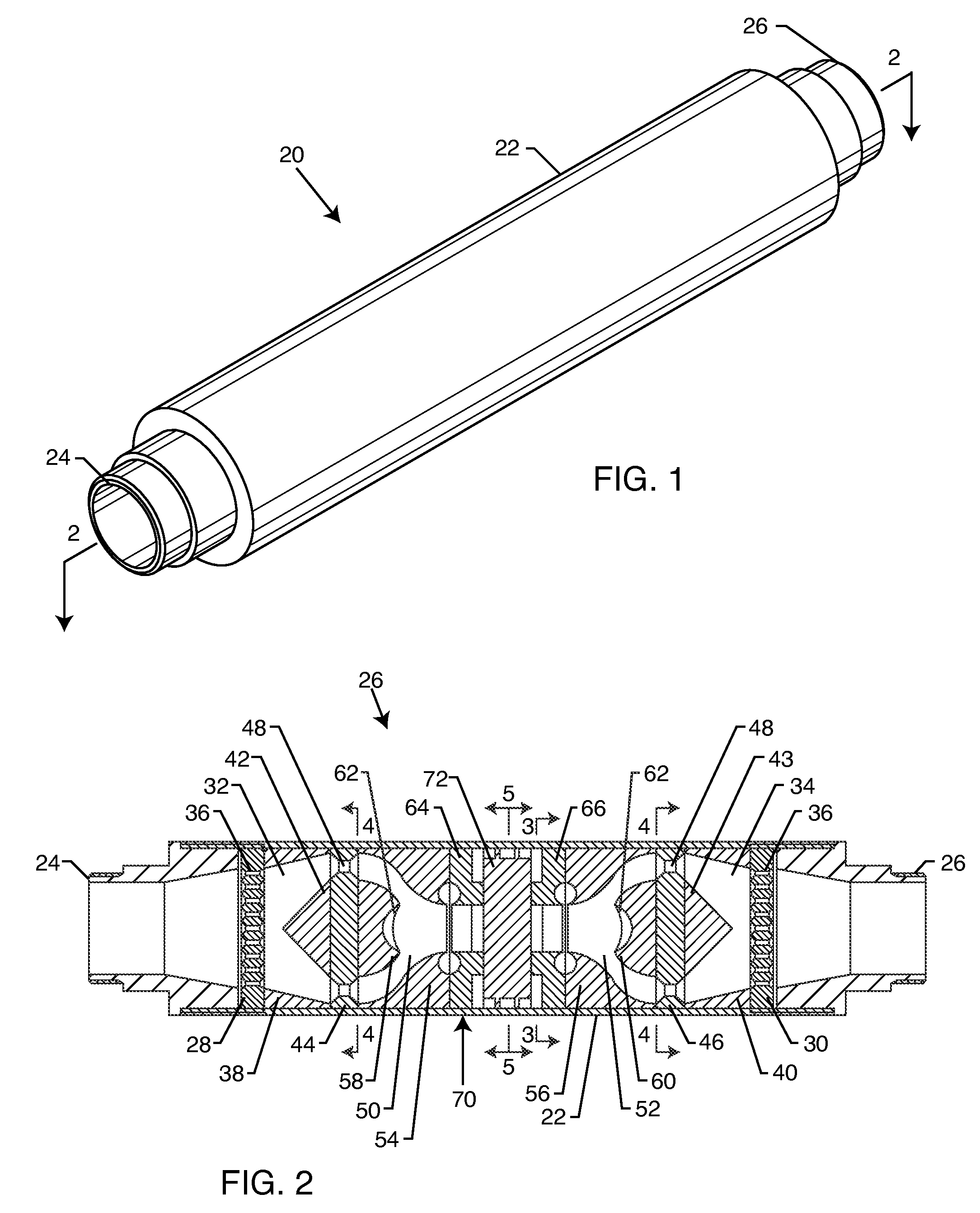
[0084]Emulsions prepared using either the flow-through cavitation device shown in FIG. 2 connected to a wheel pump or a rotor-stator cavitation device equipped with a centrifugal pump. To prepare the emulsions, six liters of vegetable oil were fed into a closed system comprised of the cavitation device and pipeline at a low pump pressure. As soon as the oil was uniformly distributed throughout the system, six liters of water were added. The feeding rate was regulated with control valves. Then the pumps were set to the maximum pressure, and the engine of the rotor-stator device was started. Each mixture was allowed to pass through the cavitation device twenty times. The cycle number has been determined based on the output of the pump and the operation time. After completing the emulsification 0.1 L of emulsion was sampled in a measuring cylinder, and the volume of oil separated from the emulsion was measured visually in 1, 5, 10, 20, 60, 120, 360 and 600 min. The obtained data is pre...

example 2

[0086]Cavitation alters physical chemical properties of fluids and may substantially improve them. It is known that the proper cavitation of crude oil may increase yield of the light fractions. Cavitation separates hydrocarbon molecules and modifies them, depending on the conditions. Crude oil was fed in the flow-through cavitation device (FIG. 2) at a rate of 220 L / min (58 gal / min) at a 60-psi pump's pressure. The oil was passed through the cavitation device twenty times and then was distilled at ambient pressure. The collected data is summarized in Table 2. It can be seen that the crude oil that was processed with the inventive flow-through cavitation system is distilled at a lower temperature. The data suggest that the cavitation of crude oil has changed its properties, resulting in an increase in light fraction yield.

[0087]

TABLE 2Comparison of distillation yield of the preliminary cavitated crude oilwith that of the non-treated crude oil.T, ° C.Crude oil processedwith the cavita...


PUM

PropertyMeasurementUnit
temperatureaaaaaaaaaa
pressureaaaaaaaaaa
velocityaaaaaaaaaa

Abstract

A method for processing a fluidic mixture in a multi-stage hydrodynamic cavitation device is disclosed. The fluidic mixture is introduced to an inlet and passed through a flowpath having at least ten cavitation zones. The fluidic mixture is exposed to cavitation inducing features in each of the at least ten cavitation zones to induce cavitation bubbles, which bubbles are then collapsed between every two adjacent of the at least ten cavitation zones. The multi-stage hydrodynamic cavitation device for processing the fluidic mixture has a generally cylindrical housing with an inlet, an outlet, a flowpath therebetween, and a plurality of cavitation zones along the flowpath. Two or more of the cavitation zones along the flowpath comprise a disk multi-jet nozzle having a plurality of through channels disposed across the surface thereof, wherein each channel includes expansions and contractions of its cross-sectional area along its length.

Description

BACKGROUND OF THE INVENTION[0001]The invention relates generally to mixers and cavitation devices that are utilized for processing heterogeneous and homogeneous fluids through the controlled formation of cavitation bubbles that serve as independent chemical mini-reactors, and uses the energy released upon implosions of these cavities to alter quickly said fluids. The device may find applications in petroleum, chemical, pharmaceutical, fuel, food and other industries to prepare solutions, emulsions, and dispersions and to improve mass and heat transfer processes.[0002]More particularly, the invention relates to modifying complex fluids composed of a number of different compounds and utilizes cavity implosion energy to improve said fluids' homogeny, viscosity, and / or other physical characteristics, alter their chemical composition by converting compounds, and obtain upgraded, more valuable products.[0003]It has been reported that the elevated pressure, increased temperature and vigoro...

Claims


Application Information

Patent Timeline
Patent Type & Authority Patents(United States)
IPC IPC(8): B01F5/06B01F33/40
CPCB01F5/0268B01F5/0603B01F5/0656B01F5/0657B01F5/0682B01F5/0688B01F13/1013B01F13/1016B01J19/008B01J19/26C10G9/007C10G15/08C10G31/06B01F25/25B01F25/421B01F25/434B01F25/4341B01F25/45B01F25/4521B01F33/811B01F33/81
Inventor GORDON, ROMANGORODNITSKY, IGORPROMTOV, MAXIM
Owner CAVITATION TECH
Why Eureka
Try Eureka