Electromechanical drive for actuating valves

a technology of electromechanical drive and actuating valve, which is applied in the direction of valve details, motors, couplings, etc., can solve the problems of large changes in speed in steam turbines, complex mechanical piping, and high requirements that cannot be fulfilled with pneumatic drives, and achieve simple and robust control of speed and/or rotor position of electromotors, and reliable adjustment of speed and/or rotor position

Active Publication Date: 2011-11-01
VOITH TURBO GMBH & CO KG
View PDF21 Cites 10 Cited by
  • Summary
  • Abstract
  • Description
  • Claims
  • Application Information

AI Technical Summary

Benefits of technology

[0012]In a mounted state of the drive in accordance with an embodiment of the present invention, the spindle nut is positioned in a stationary manner relative to the valve to be actuated, so that the forces occurring during the actuation of the valve can be absorbed. By disengaging the clutch, quick-action closing of the valve is facilitated because no force needs to be exerted for co-rotation of the motor axis of the electromotor during the quick-action closing. By controlling and / or adjusting the rotor position of the motor axis of the electromotor, the position of the piston rod, and thus a valve opening, can be set precisely. The position pick-up is used to determine the position of the piston rod, which allows feedback for monitoring the control. The position pick-up can be arranged as any component, such as a sensor, having an output signal from which the position of the piston of the piston rod can be calculated and / or derived by an indirect method.
[0013]The actuator in accordance with the present invention can be used especially for actuating lift valves, preferably steam valves in steam turbines. The actuator can be used to actuate valves in steam engines with a purely electromechanical drive. Hydraulic and pneumatic supply can thus be omitted. The drive contains all required components and functions in order to fulfill the special requirements which are given in the actuation of valves in steam turbines. This opens the possibility to simply replace existing hydraulic or pneumatic drives by maintaining the usual functionalities and interfaces. The electromechanical actuator according to the present invention for steam valves avoids the disadvantages of known actuators for steam valves, with all necessary requirements placed on an actuator for steam valves being maintained. The electromechanical drive in accordance with the invention merely requires electric power for its operation and can be arranged as a very compact arrangement which contains all elements that are necessary for performing the function necessary for an actuator unit of a steam valve.
[0016]When the linear unit includes at least one shock absorber for absorbing the kinetic energy of the piston rod during a displacement of the piston rod in the direction of the closing valve, damage to the linear unit during a quick-action closing process can be avoided.
[0019]The transmission further ensures that the motor axis and the piston rod can be arranged next to one another in parallel in a spatial respect, through which a very compact arrangement of the electromechanical drive in accordance with the present invention is achieved.
[0020]Preferably, the position pick-up of the position of the piston rod includes a linear displacement transducer in the linear unit which is arranged for measuring the position of the piston rod in the screw nut with power-transmission thread. The position of the piston rod and thus the valve opening position of the valve to be actuated can thus be measured directly, leading to a very reliable adjustment of the speed and / or the rotor position of the electromotor. Alternatively or additionally, the position pick-up can include a speed or rotor-position sensor of the electromotor. The speed and rotor-position sensor can be arranged, for example, as incremental position transducer or resolver. When the rotor position of the electromotor and its speed are known, the position of the piston rod can easily be calculated from the same.
[0021]A simple and robust control of the speed and / or the rotor position of the electromotor is enabled when the control unit includes a frequency converter. The frequency converter is dimensioned in such a way that the desired control is achieved. A spherical bearing fixture for connection with a valve to be actuated is advantageously provided at the free end of the piston rod. The piston rod then need not be aligned in true alignment with the valve.

Problems solved by technology

A precise low-hysteresis low-level signal behavior is required especially during the synchronization of a driven generator to the electric infeed network because no damping load acts on the steam turbine and thus small changes in the stroke of the actuator on the steam valve will lead to large changes in speed in the steam turbine.
These high requirements can hardly be fulfilled with pneumatic drives.
Moreover, complex mechanical piping is necessary which leads the medium to the actuator and from there back to the oil supply.
There is always the likelihood of leakages of medium on the actuator and the piping, which is caused by improper piping or by the detachment of connecting elements by vibrations which are always present in steam turbines.
These leakages of medium can lead to fires when flammable medium reaches the hot surface of the steam turbine.
However, they are expensive, lead to higher maintenance costs, and are hazardous for the environment which is why they have not prevailed as a solution to the problem.
A further disadvantage of known actuator technology is that, in the case of electrohydraulic actuators, the mounting position cannot be chosen freely but is regularly predetermined in a fixed fashion, thus limiting the constructional freedom in the arrangement of such drives.

Method used


Image

  • Electromechanical drive for actuating valves
  • Electromechanical drive for actuating valves
  • Electromechanical drive for actuating valves

Examples


Embodiment Construction

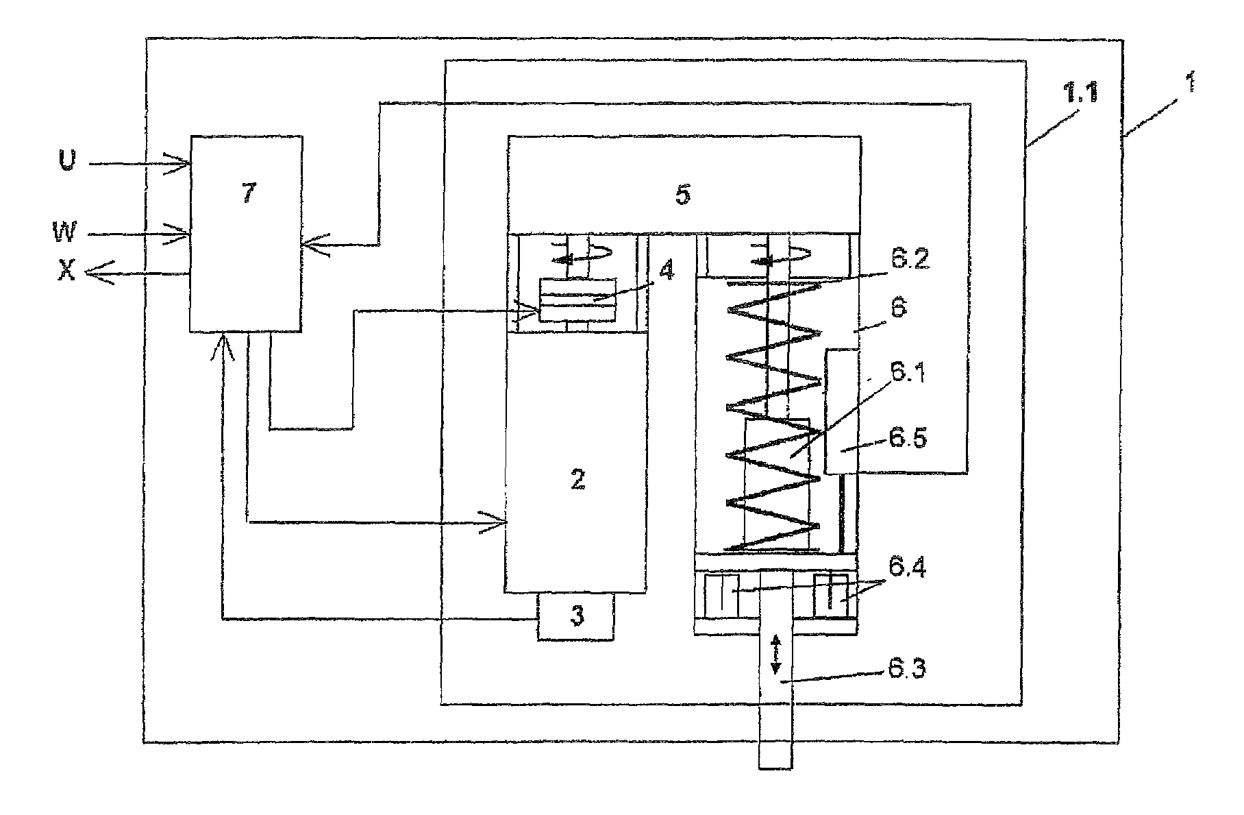
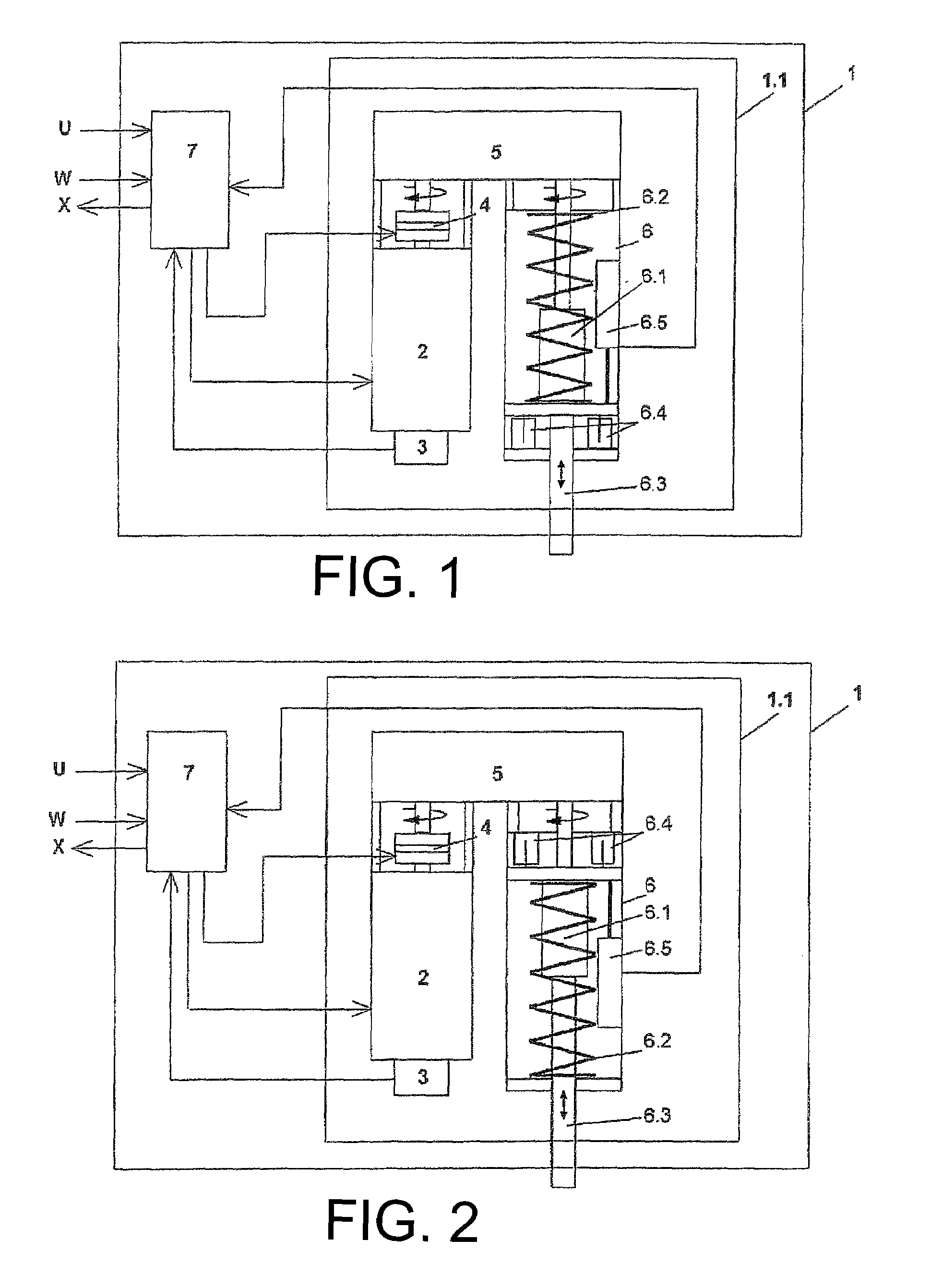
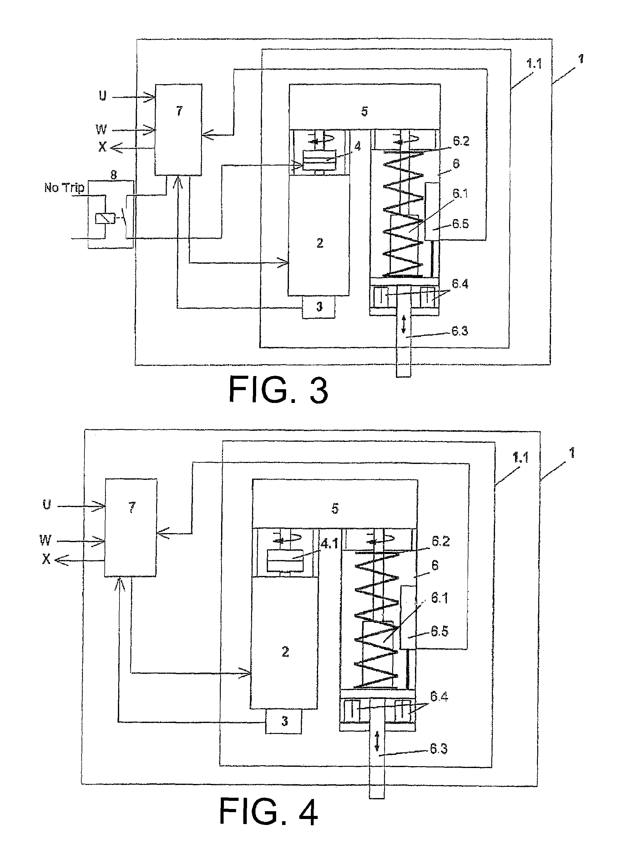
[0033]Referring now to the drawings, and more specifically to FIG. 1, there is shown a schematic illustration of an electromechanical drive 1 in accordance with an embodiment of the present invention for actuating a valve of a steam turbine, not shown in the drawing. Drive 1 includes an electromechanical actuating unit 1.1 and a control unit 7 which is arranged as a frequency converter. An electromotor 2, which is preferably arranged as a permanently excited synchronous or asynchronous motor, is triggered by way of control unit 7. Feedback for adjusting the position and the speed of the motor axis of electromotor 2 with control unit 7 is enabled by way of a speed and rotor-position sensor 3, which can be arranged as an incremental position transducer or as a resolver.

[0034]A torque exerted by the electromotor is transmitted by a gearing 5, which can be arranged as a two-stage belt drive or a toothed gear onto piston rod 6.3 of linear unit 6. Gearing 5 is simultaneously used as a hou...


PUM


Abstract

The invention relates to an electromechanical drive for actuating valves, especially in steam turbines including an electromotor, a linear unit, a clutch and an electronic control unit. The linear unit includes a piston rod which is guided in a power-transmission thread of a screw nut, and is arranged, at least in sections, as a spindle and is displaceable along its longitudinal axis for actuating the valve in the screw nut with the power-transmission thread. The clutch is arranged for transmitting a rotational movement of the motor axis of the electromotor onto the piston rod. The electronic control unit is set up to control the speed and / or rotor position of the motor axis of the electromotor depending on a control signal and an output signal of a position pick-up of the position of the piston rod in the screw nut with power-transmission thread, and / or to control the engagement and / or disengagement of the clutch depending on the control signal.

Description

BACKGROUND OF THE INVENTION[0001]1. Field of the Invention[0002]The present invention relates to an electromechanical drive for actuating valves, especially in steam turbines.[0003]2. Description of the Related Art[0004]It is known to open and close valves in steam turbines with hydraulic or pneumatic drives, for example, to actuate an actuator for this purpose with a hydraulic cylinder or pneumatic cylinder in an electrohydraulic or electropneumatic manner. Examples for such actuators are described in German Patent documents DE 30 19 602 C2 and in DE 42 36846 C2.[0005]Electrohydraulic or electropneumatic actuators are used for adjusting steam valves. Such actuators consist of a hydraulic cylinder or pneumatic cylinder which can be arranged in a single-acting or double-acting manner. A hydraulic / pneumatic control valve triggering the same is arranged as a 3 / 3 or 4 / 3 directional control valve and a position-sensing and a closed-loop control mechanism for the hydraulic cylinder or pne...

Claims


Application Information

Patent Timeline
Patent Type & Authority Patents(United States)
IPC IPC(8): F04D1/04F04D17/06F04D29/42F04D5/00
CPCF01D17/145F16K31/046F16K31/047
Inventor GOLL, ARMIN
Owner VOITH TURBO GMBH & CO KG
Why Eureka
Try Eureka