Motor drive circuit

a technology for motors and drives, applied in safety/protection circuits, emergency protection arrangements for automatic disconnection, dc source parallel operation, etc., can solve the problems of high cost, high cost, time-consuming, etc., and achieve the effect of low failure probability

Active Publication Date: 2011-11-01
TRW LIMITED
View PDF22 Cites 89 Cited by
  • Summary
  • Abstract
  • Description
  • Claims
  • Application Information

AI Technical Summary

Benefits of technology

[0021]This motor circuit ensures that any short circuits of the motor phases to ground or one of the supply voltages will not cause a short across the DC link filter, and so prevent a catastrophic failure of the DC link filter. In addition, it removes one of the possible short circuit paths that may cause the motor to enter a braking mode of operation, which could present a safety hazard.
[0022]The motor may comprise a high reliability motor. By this we mean that the motor, ...

Problems solved by technology

A problem with this electrical power-assisted steering system is that a fault occurring in the motor drive or control circuits can cause an error condition which is unacceptable in a vehicle steering system, where safety is critical.
This fault would result in a phase of the motor becoming permanently energised and cause the motor to become permanently attracted to a particular position, tending to clamp the steering column in position and resist rotation.
This would be readily apparent to the driver, and is clearly undesirable.
This situation could occur if the bridge driver is at fault, or if a short circuit occurs across the drive stage transistors, or if a short circuit occurs across the DC link supply.
However, the clutch is costly and bulky, and additional test procedures must also be incorporated to check that the clutch can still be disengaged should it be necessary to do so, whi...

Method used


Image

  • Motor drive circuit
  • Motor drive circuit
  • Motor drive circuit

Examples


Embodiment Construction

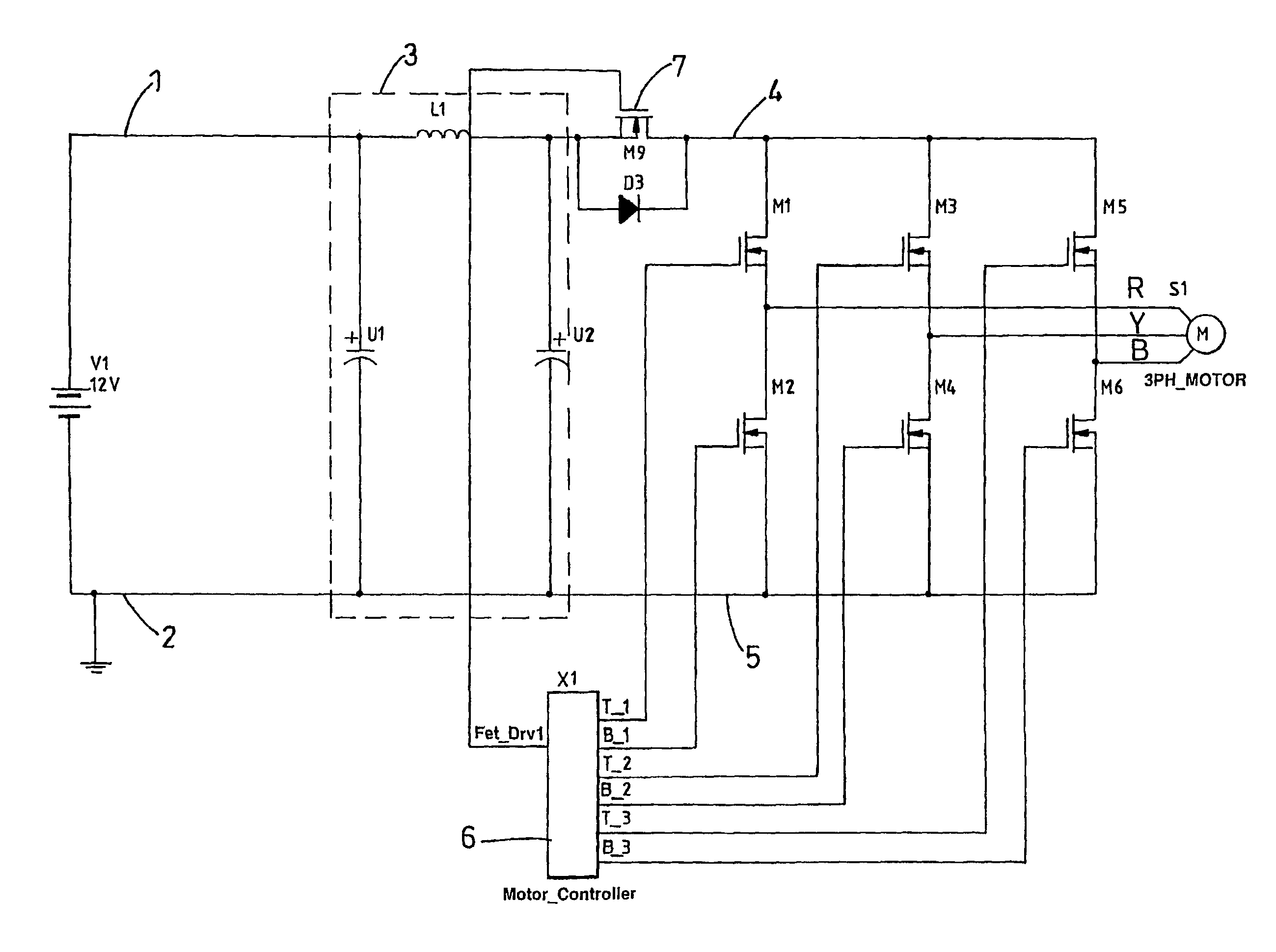
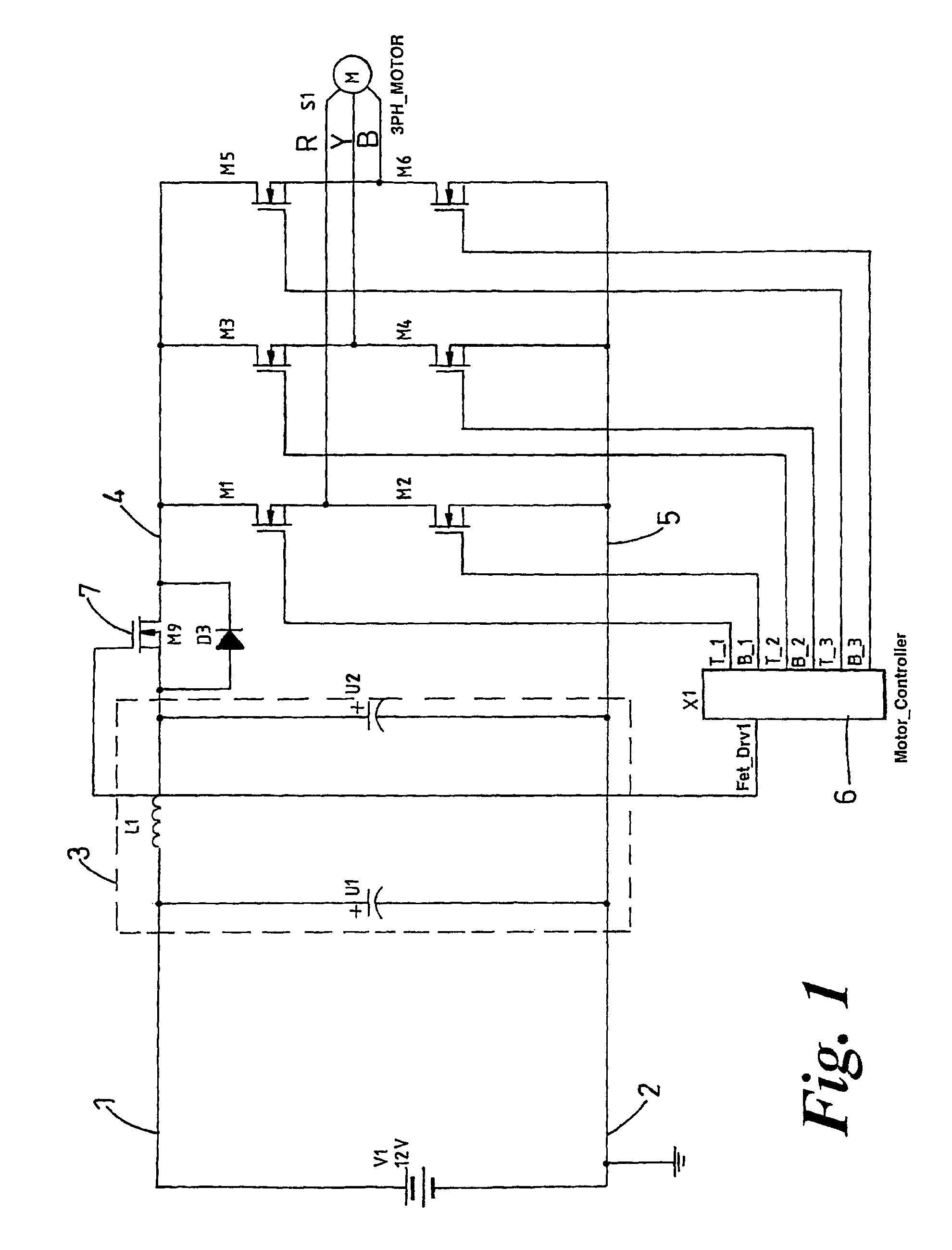
[0035]FIG. 1 illustrates a part of an electrical power-assisted steering (EPAS) system for use in a vehicle which incorporates an electric motor. The drive circuit comprises a pair of input terminals 1,2 for connection to the positive and negative supply rails of the vehicle. A DC link filter 3 is connected between the two terminals 1,2. It comprises two capacitors U1 and U2 connected in parallel between the two input terminals, with an inductor connected in series with one of the capacitors U2. An output of the DC link filter 3, taken from between the inductor L1 and capacitor U2 is fed to a rail 4 which carries current to several motor drive sub-circuits. The sub-circuits are connected as a three phase bridge, with each phase of the bridge comprising a motor drive sub-circuit having a transistor M1-M6 connected to one of the rail 4 or to ground 5. A top transistor M1 is connected between the first end of a respective phase winding (R, Y, B) and the positive supply rail 4, and a bo...


PUM


Abstract

A motor drive circuit comprises positive and negative input terminals for connection of the motor circuit to a DC supply, a DC link filter connected between the input terminals: an electric motor having at least two phases, a plurality of motor drive sub-circuits, each connected to a respective phase of the electric motor and which each control the flow of current into or out of the respective phase of the motor that has been drawn from the supply through the DC link filter, and a switching means provided in the electrical path between the DC link filter and the electric motor drive sub-circuits, the switching means being movable between a closed position in which it connects the DC link filter to the motor drive sub-circuits, and an open position which isolates the DC link filter from the motor drive sub-circuits.

Description

CROSS-REFERENCE TO RELATED APPLICATIONS[0001]This application is the National Phase of International Application PCT / BB2006 / 00302 filed Aug. 15, 2006 which designated the U.S. and that International Application was published in English under PCT Article 21 (2) on Feb. 22, 2007 as International Publication Number WO 2007 / 020419 A1. PCT / BB2006 / 00302 claims priority to UK Patent Application No. 0516738.2, filed Aug. 16, 2005. Thus, the subject nonprovisional application claims priority to UK Patent Application No. 0516738.2, filed Aug. 16, 2005. The disclosures of both applications are incorporated herein by reference.BACKGROUND OF THE INVENTION[0002]This invention relates to a motor drive circuit which is especially, but not exclusively, suited to use in an electrical power-assisted steering (EPAS) system for a vehicle.[0003]EPAS systems are known of the kind comprising an electric motor connected through a gearbox to act on a steering mechanism of the vehicle. For example, the gearbo...

Claims


Application Information

Patent Timeline
IPC IPC(8): H02J3/32H02H7/122H02J7/00
CPCH02H7/1225H02J7/0031
Inventor MCLEAN, ANDREWBOLTON, JOHN ANTHONY
Owner TRW LIMITED
Why Eureka
Try Eureka