Electron beam controller of an x-ray radiator with two or more electron beams

a technology of electron beams and electron beams, which is applied in the direction of x-ray tube multi-cathode assembly, electrical discharge tubes, x-ray tube multi-cathode assemblies, etc., can solve the problems of not using characteristic x-ray radiation the basic principle of x-ray generation has not changed, and the x-ray beam cannot be used in the medical use of x-ray tubes, etc., to improve the x-ray

Active Publication Date: 2011-11-08
SIEMENS HEALTHCARE GMBH
View PDF6 Cites 8 Cited by
  • Summary
  • Abstract
  • Description
  • Claims
  • Application Information

AI Technical Summary

Benefits of technology

[0010]An object of the invention is to provide an x-ray tube and a method for operating an x-ray tube of the aforementioned type that enable a high x-ray dose power with a long lifespan. Furthermore, the x-ray dose power can be varied quickly.
[0015]In order to achieve an optimally good matching of the individual deflection units among one another, in a particularly preferred embodiment the individual deflection units are controlled via a common control unit. This control unit normally comprises an evaluation unit and evaluates the intensity distribution of the x-rays. It subsequently sends the commands (optimized for each individual deflection unit) for deflection of the electron beams to the deflection units. The current data about the distribution of the x-ray dose can thereby be received and evaluated in real time. A control of the deflection units that is tailored to its necessity (and therefore a particularly good optimization of the source surface of the x-rays) is thus possible, whereby an even further improved focusing of the resulting x-ray beams from multiple emitters is enabled.
[0016]In order to also obtain an optimally variable x-ray dose in addition to the high x-ray dose that is possible via the focusing of multiple x-ray beams, in an advantageous embodiment the emitters are designed to generate electron beams of different intensity. It is thereby possible to easily adapt the electron beam dose to the desired values by suitable control of the emitters or activation of the emitters. A refocusing of the resulting x-ray beam is normally not required or, respectively, is conducted automatically by the control unit.
[0018]To improve the focusing of the x-ray beams, in a preferred embodiment the individual deflection units are connected with a common control unit. This control unit is advantageously connected with a detector capable of spatial resolution and measuring the intensity distribution, which detector measures the intensity distribution of the x-rays and correspondingly relays these to the control unit or, respectively, to the evaluation unit comprising the control unit. The control unit then sends control commands to the individual deflection units in order to thus achieve a focusing of the individual x-ray beams on a common focal spot.
[0019]An advantage achieved with the invention is that a focusing is possible through the use of the intensity distribution of the superimposed x-ray beams, even when the resulting x-ray beam is originally generated by multiple electron beams. Both a high x-ray dose power and a fast variation of the x-ray dose are thereby possible.

Problems solved by technology

In the course of time, tech improvements have also been made to the x-ray tubes but these changes have not changed the basic principle of the generation of x-rays.
However, this characteristic x-ray radiation is not used (or is used only in small part) for image generation in an x-ray radioscopy, with the exception of mammography and crystal analysis.
The third generated radiation type is the transition radiation or Lilienfeld radiation, but this cannot be employed in the medical use of x-ray tubes.
However, for the most part this cannot be achieved in the x-ray tube due to structural and material-related limitations.
In particular, the lifespan of the emitters is severely shortened given the generation of very high electron currents given lower high voltage values.
Furthermore, an optimal focusing of the x-ray beam generated in the anode cannot occur at high electron currents since an expansion of the focal spot size on the anode ensues due to the repulsion of the electrons among one another due to space charge effects.

Method used


Image

  • Electron beam controller of an x-ray radiator with two or more electron beams
  • Electron beam controller of an x-ray radiator with two or more electron beams

Examples


Embodiment Construction

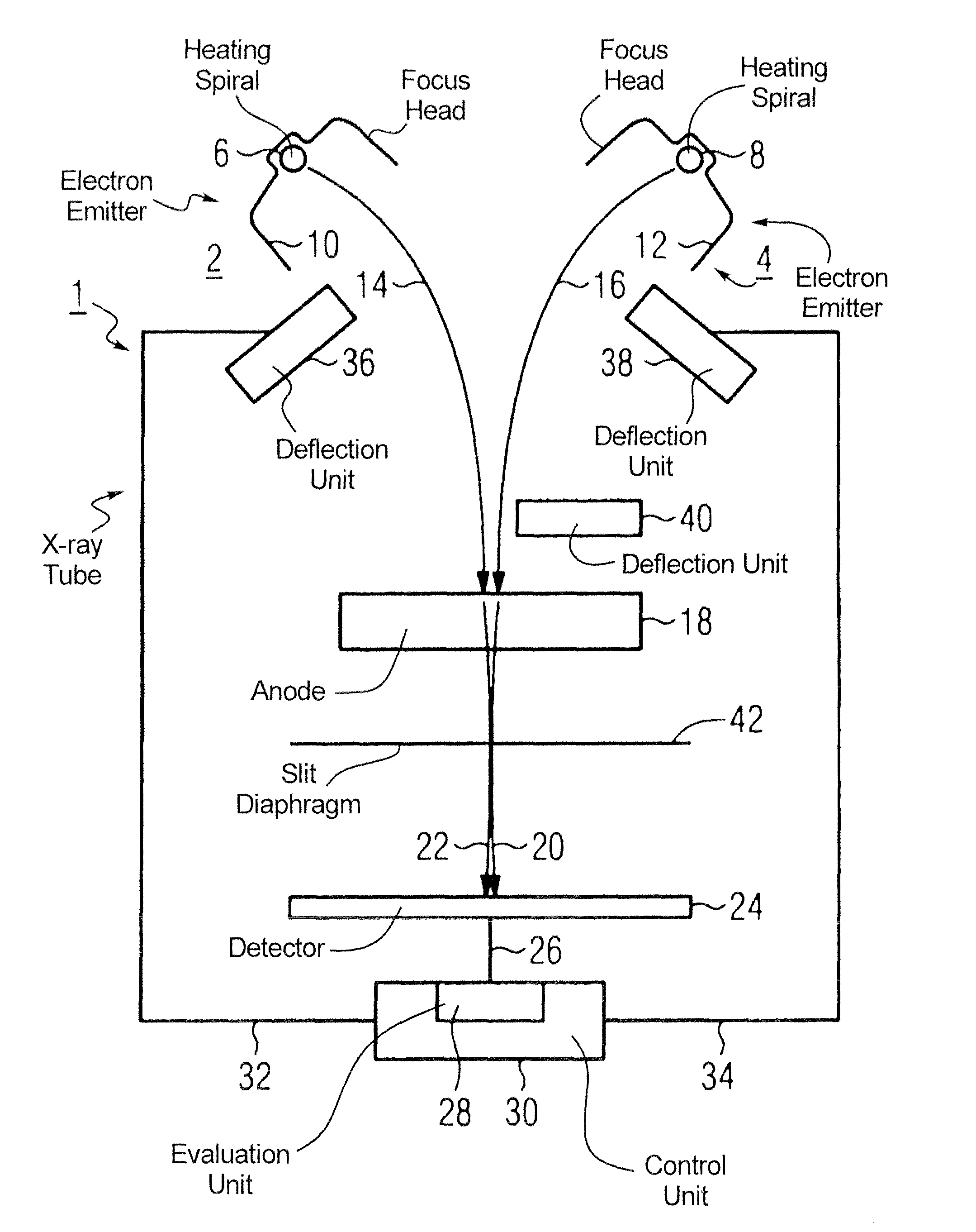
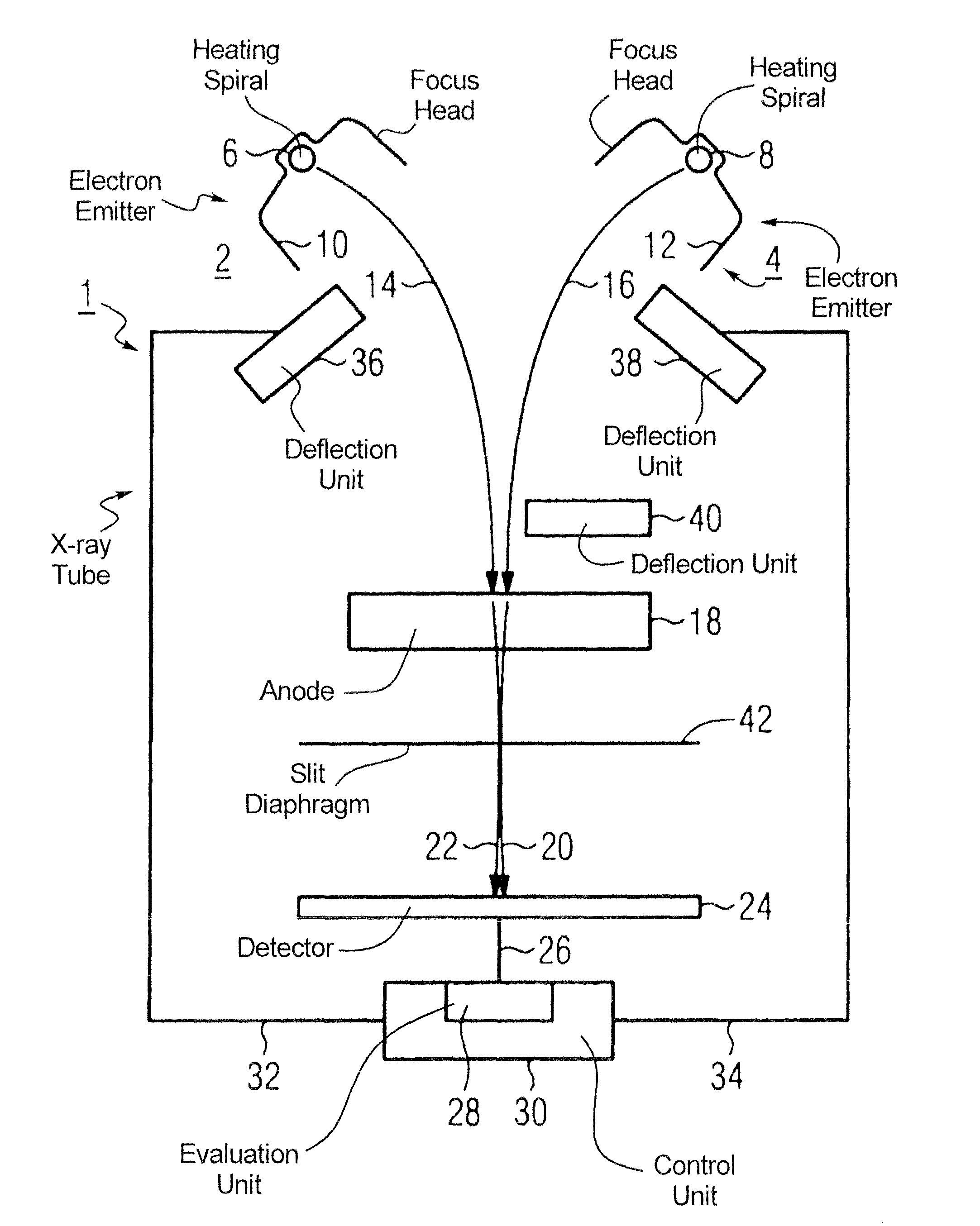
[0021]The x-ray tube 1 according to the FIGURE has two emitters 2, 4. These emitters 2, 4 respectively have heating spirals 6, 8 and focus heads 10, 12 for generation of electron beams 14, 16. These electron beams 14, 16 are deflected onto an anode 18. The electron beams 14, 16 are braked in the anode 18 and in particular generate x-ray bremsstrahlung in addition to the characteristic x-ray radiation and the transition radiation. The x-ray beams 20, 22 generated by this braking procedure in the anode 18 are mapped by a slit diaphragm 42 to a detector 24 with spatial resolution. This detector 24 measures the spatial distribution of the x-ray dose power or the intensity of the two superimposed x-ray beams 20, 22. The data measured in this way are sent from the detector 24 via a data line 26 to the evaluation unit 28 of a control unit 30. The evaluation unit 28 evaluates the data of the detector 24 with regard to the different moments of the distribution and passes the result to the co...


PUM


Abstract

An x-ray tube has a number of emitters that generate respective electron beams, and has a common anode at which the electron beams strike on a surface to generate x-rays. A high x-ray dose power with a long lifespan are achieved while being able to quickly vary the x-ray dose power by using a superimposed intensity distribution from the x-ray beams, which is measured by a detector, to optimize the x-ray beams on the surface.

Description

BACKGROUND OF THE INVENTION[0001]1. Field of the Invention[0002]The present invention concerns a method for operation of an x-ray tube of the type having a number of emitters that generate respective electron beams, and an anode at which the electron beams strike on a surface to generate x-rays. The invention additionally concerns an x-ray tube with a number of emitters and a common anode.[0003]2. Description of the Prior Art[0004]An x-ray tube in its simplest form is composed of a cathode and an anode that are situated in a vacuum within a sealed glass body. In high-power tubes as they are used in computed tomography (CT) and angiography, the vacuum container is formed of metal which withstands significantly greater heat effects. In the course of time, tech improvements have also been made to the x-ray tubes but these changes have not changed the basic principle of the generation of x-rays.[0005]To generate the x-rays, electrons are emitted from the cathode (the emitter) and are ac...

Claims


Application Information

Patent Timeline
Patent Type & Authority Patents(United States)
IPC IPC(8): H01J35/06
CPCH01J35/06H01J35/14H01J35/30H01J2235/068H01J35/153H05G1/52
Inventor FREUDENBERGER, JOERGNEUMEIER, ERNST
Owner SIEMENS HEALTHCARE GMBH
Why Eureka
Try Eureka