Exhaust heat recovery apparatus

a heat recovery apparatus and exhaust heat technology, applied in the direction of lighting and heating apparatus, machines/engines, laminated elements, etc., can solve the problems of reducing yield and increasing weight, and achieve the effects of improving productivity and yield, increasing the surface area of boiling and evaporating operation fluid, and simplifying the tube structur

Inactive Publication Date: 2011-11-15
DENSO CORP
View PDF6 Cites 6 Cited by
  • Summary
  • Abstract
  • Description
  • Claims
  • Application Information

AI Technical Summary

Benefits of technology

[0007]The present invention is made in view of the foregoing matter, and it is an object of the present invention to provide an exhaust heat recovery apparatus having an evaporation unit that has a sufficient surface area for boiling an operation fluid and is capable of improving productivity and yields.
[0009]Accordingly, the wet area of the operation fluid in the tube is increased by the wet area increasing member, which is provided as a separate member. That is, the surface area for boiling and evaporating the operation fluid is increased without processing the tube such as by cutting. Further, because the structure of the tube is simplified, productivity and yields improve.

Problems solved by technology

The increase of the thickness of the tube walls results in an increase of weight and a reduction of yields.

Method used


Image

  • Exhaust heat recovery apparatus
  • Exhaust heat recovery apparatus
  • Exhaust heat recovery apparatus

Examples


first embodiment

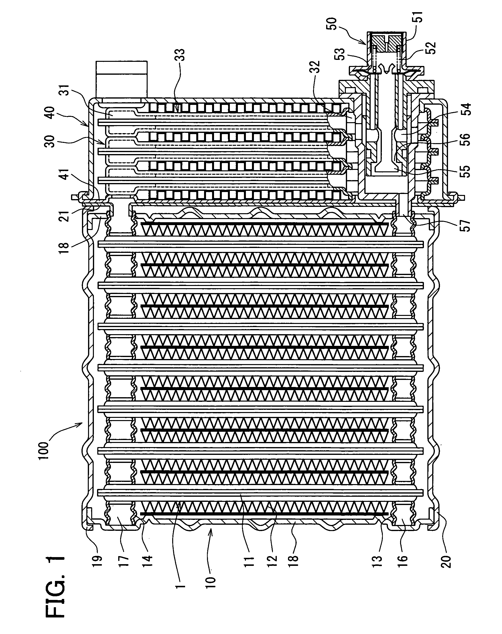
[0017]Referring to FIG. 1, an exhaust heat recovery apparatus 100 of the first embodiment is, for example, employed in a vehicle that is driven by an engine, such as a water-cooled internal combustion engine. The exhaust heat recovery apparatus 100 is disposed on an exhaust heat recovery circuit through which an engine coolant flows and an engine exhaust pipe through which an exhaust gas generated by fuel combustion flows to be exhausted from the vehicle.

[0018]The engine is in communication with a radiator circuit through which an engine coolant flows for cooling the engine, the exhaust heat recovery circuit as a circuit separated from the radiator circuit, and a heater circuit through which the coolant flows as a heat source for heating air for an air conditioning operation.

[0019]The exhaust heat recovery circuit diverges from an engine outlet portion of the radiator circuit. That is, the exhaust heat recovery circuit diverges from the radiator circuit at a position downstream of t...

second embodiment

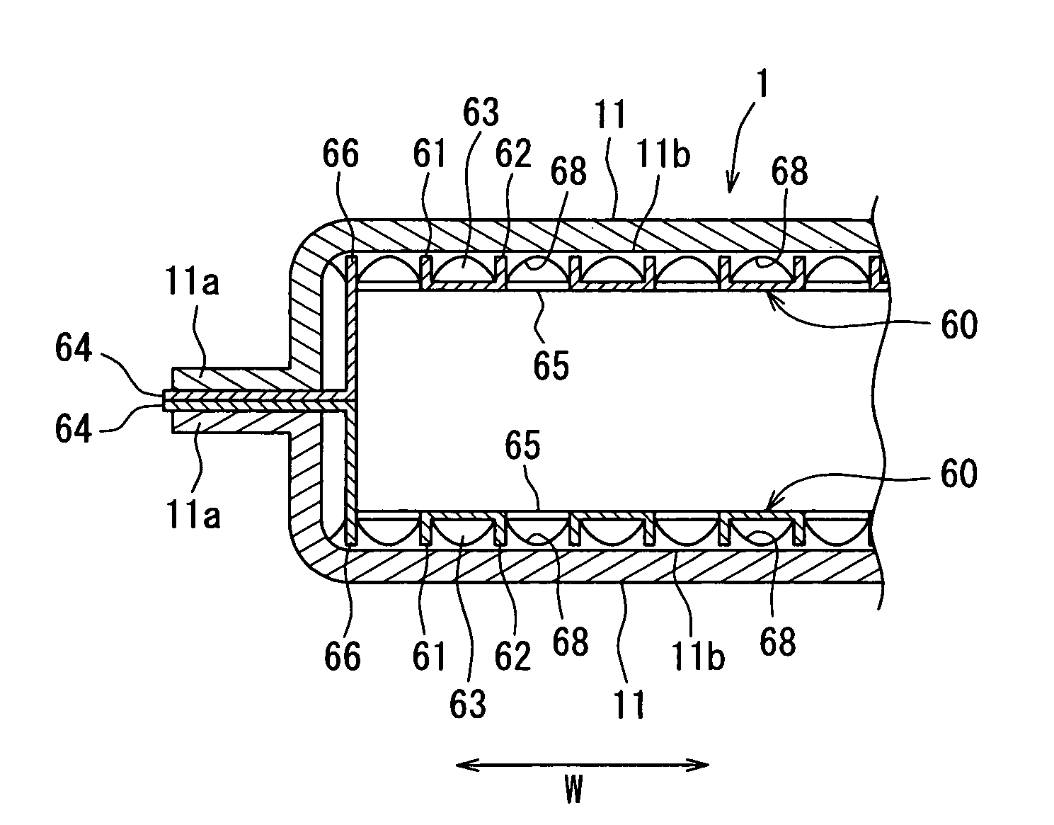
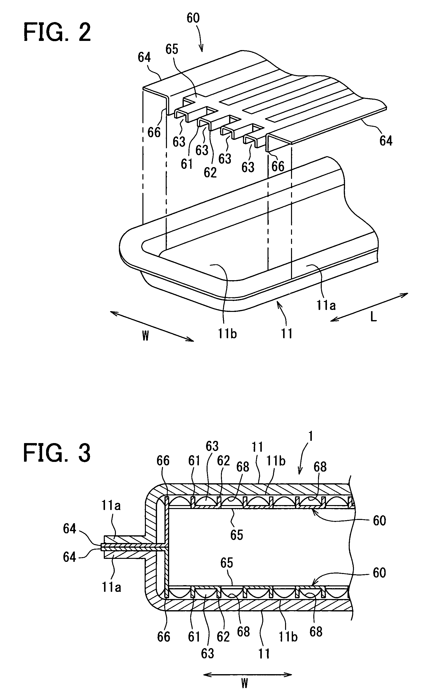
[0069]A second embodiment of the present invention will be described with reference to FIG. 5. In the second embodiment, the tube 11 has a groove plate 70 as the wet area increasing member, in place of the groove member 60 of the first embodiment. Hereinafter, components similar to those of the first embodiment will be indicated by the same numerals and will not be described further. In the present embodiment, components and structures of the exhaust heat recovery apparatus 100 other than the wet area increasing member are similar to those of the first embodiment. Thus, the similar effects as the first embodiment will be provided also in the present embodiment.

[0070]As shown in FIG. 5, the groove plate 70 is a plate member and has projections 71 and grooves 72. The projections 71 and the grooves 72 are alternately arranged in the widthwise direction W. The projections 71 and the grooves 72 extend in the lengthwise direction L, and have the substantially equal length to the length of...

third embodiment

[0078]A third embodiment of the present invention will be described with reference to FIG. 6. In the third embodiment, the tubes 11 have waved plates 80 as the wet area increasing members. Component parts and structures of the exhaust heat recovery apparatus 100 other than the wet area increasing members are similar to those of the first embodiment. Thus, the similar effects as the first embodiment will be provided also in the third embodiment.

[0079]The wave plate 80 has a wave form and alternately forms projections 81 and grooves 82 in the widthwise direction W. The projections 81 and the grooves 82 extend in the lengthwise direction L and have the substantially equal length as the length of the inner surface 11b. Further, slits may be formed in the longitudinal direction of the projections 81 by pressing such as punching.

[0080]The wave plate 80 is formed by pressing a roll material using a pressing device or the like. That is, the projections 81, the grooves 82, the slits and the ...


PUM


Abstract

An exhaust heat recovery apparatus includes an evaporation unit and a condensation unit communicated with the evaporation unit such that an operation fluid circulates therein. The evaporation unit is disposed in a first fluid passage through which a first fluid flows, and performs heat exchange between the first fluid and the operation fluid, thereby evaporating the operation fluid. The condensation unit is disposed in a second fluid passage through which a second fluid flows, and performs heat exchange between the second fluid and the operation fluid. The exhaust heat recovery apparatus further includes a wet area increasing member in a tube of the evaporation unit for increasing a wet area of the operation fluid due to surface tension of the operation fluid. The wet area increasing member is disposed adjacent to an inner surface of the tube and has extension surfaces extending in directions intersecting with the inner surface.

Description

CROSS REFERENCE TO RELATED APPLICATION[0001]This application is based on Japanese Patent Application No. 2007-35328 filed on Feb. 15, 2007, the disclosure of which is incorporated herein by reference.FIELD OF THE INVENTION[0002]The present invention relates to an exhaust heat recovery apparatus.BACKGROUND OF THE INVENTION[0003]It is known to recover heat of exhaust gas exhausted from an exhaust system of a vehicular engine based on the principle of heat pipe and use the recovered heat for other purposes such as for warming up the engine. As an example of an exhaust heat recovery apparatus, Japanese Unexamined Patent Application Publication No. 4-45393 describes a looped heat pipe heat exchanger.[0004]The disclosed heat exchanger includes a closed looped circulation passage filled with an internal heat-transfer fluid, an evaporation unit disposed on the circulation passage for evaporating the internal heat-transfer fluid therein by receiving external heat and a condensation unit disp...

Claims


Application Information

Patent Timeline
Patent Type & Authority Patents(United States)
IPC IPC(8): F28F3/06
CPCF01N5/02F28D15/043F01N2240/22F28D15/0266F28D21/0003F28F1/126Y02T10/16Y02T10/12
Inventor MIYAGAWA, MASASHIKOHARA, KIMIO
Owner DENSO CORP
Why Eureka
Try Eureka