Mode hopping swept frequency laser for FD OCT and method of operation
a swept frequency, laser technology, applied in lasers, semiconductor lasers, instruments, etc., can solve the problems of high speed tuning and maintaining long coherence length that is difficult to achieve in conventional tunable lasers, is bulky, and requires a short cavity length, e.g. 10 to 30 millimeters (mm), and achieves high speed, high tuning speed, and the effect of increasing the tunable laser's dwell tim
- Summary
- Abstract
- Description
- Claims
- Application Information
AI Technical Summary
Benefits of technology
Problems solved by technology
Method used
Image
Examples
first embodiment
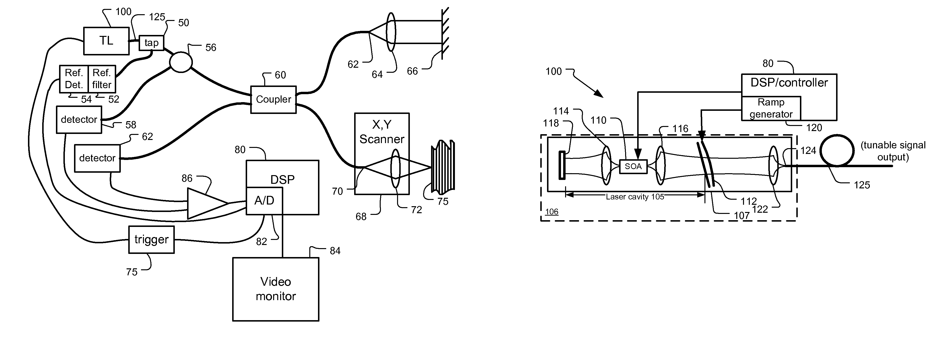
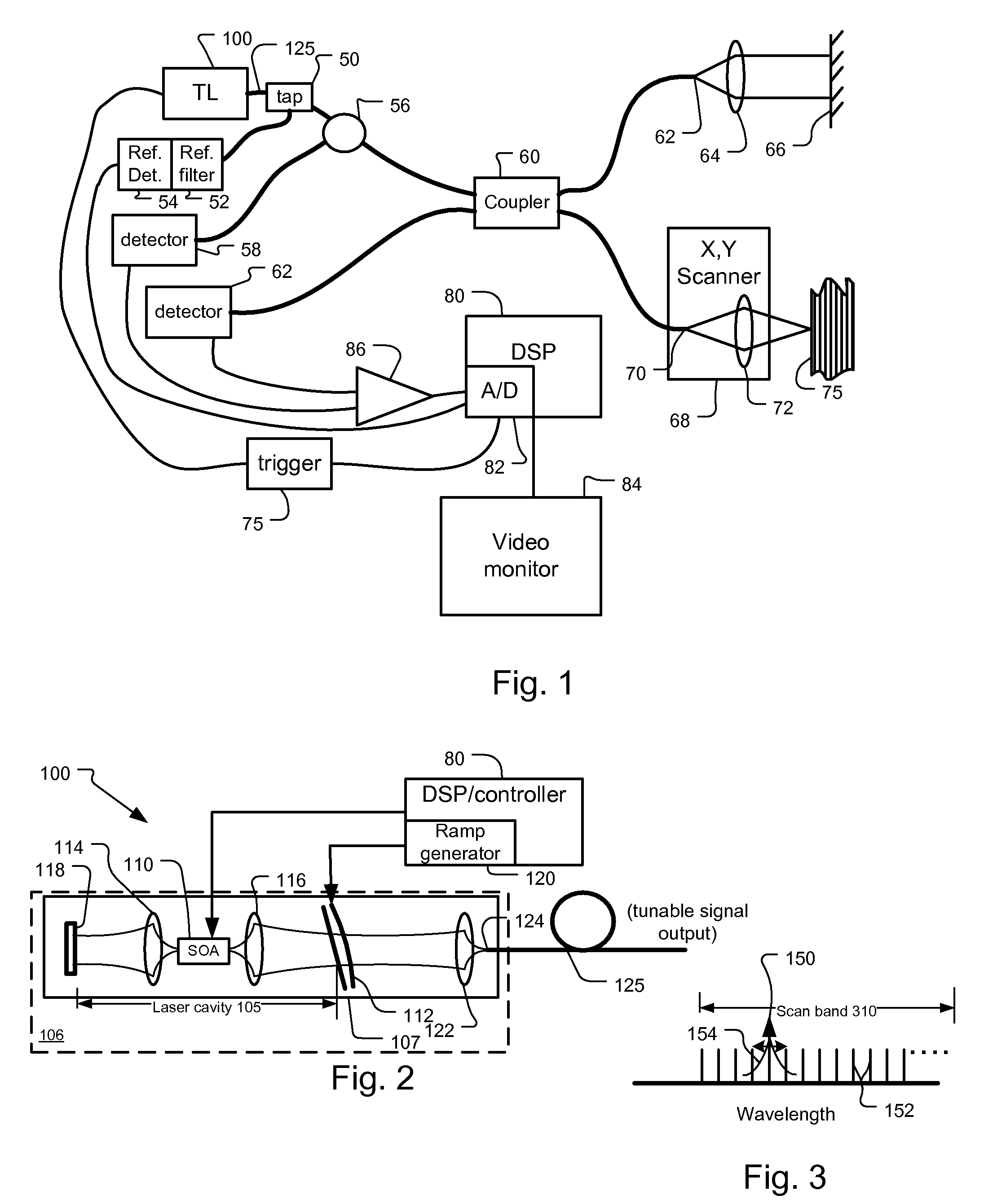
[0037]FIG. 2 shows the tunable semiconductor laser 100 according to the invention.
[0038]In more detail, the tunable laser 100 comprises a semiconductor gain chip 110 that is paired with a microelectromechanical (MEMS) angled reflective Fabry-Perot tunable filter 112 to create external cavity tunable laser (ECL).
[0039]The semiconductor optical amplifier (SOA) chip 110 is located within a laser cavity 105. In the current embodiment, both facets of the SOA chip are angled and anti-reflection (AR) coated, providing parallel beams from the two facets.
[0040]Specifically, each end facet of the SOA 110 has associated lenses 114, 116 that are used to couple the light exiting from either facet of the SOA 110. The first lens 114 couples the light between the back facet of the SOA 110 and a mirror 118. Light exiting out the front facet of the SOA 110 is coupled by a second lens 116 to the reflective Fabry-Perot tunable filter 112.
[0041]The angled reflective Fabry-Perot filter is a multi-spatial...
second embodiment
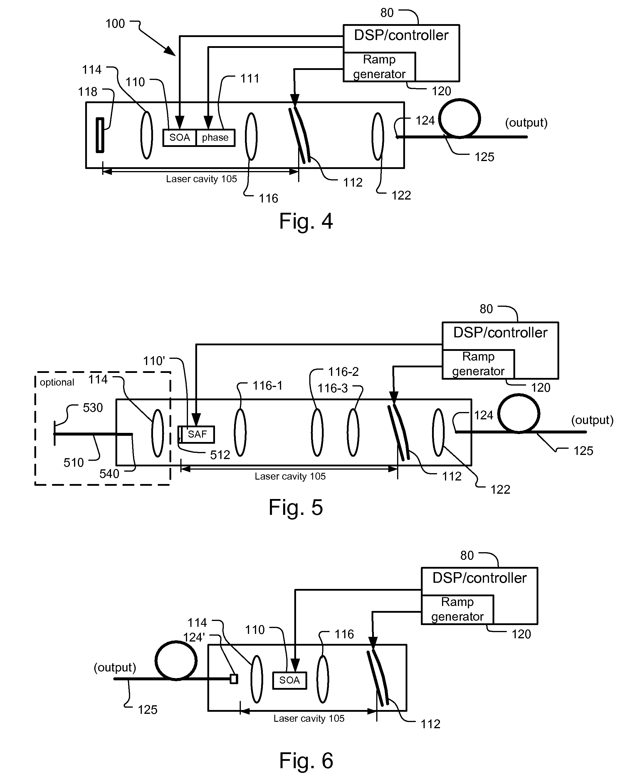
[0049]FIG. 4 shows the mode hopping tunable laser 100. This includes a second semiconductor chip section 111 that functions as an intra cavity phase or dispersion compensator, which is integral with the semiconductor gain medium in a preferred embodiment. Specifically, there is a certain amount of dispersion during scanning, which implies variation of cavity mode frequency spacing. The cavity 105 is not all air; there is refractive index dispersion in the laser chip, lenses, optical coatings. Also, laser threshold changes over the tuning range. Thus, there will typically be higher carrier density inside the gain chip 110, when it is tuned to the edges of the spectrum. This increased carrier density decreases the chip's refractive index and thereby causes a dispersion-like effect.
[0050]The phase compensator 111 controls its refractive index and thus the optical length of the cavity as compensation.
[0051]In other embodiments, the compensator includes an electro-optic medium.
[0052]In o...
third embodiment
[0053]FIG. 5 shows the mode hopping tunable laser 100. This uses a reflective SOA or single angled facet (SAF) chip 110′. Specifically, the back normal facet 512 of the semiconductor amplifier 110′ is reflective to define one end of the laser cavity 105. On the front angled non-reflective facet, a series of three lenses 116-1, 116-2, 116-3 is used to collimate the output of the semiconductor amplifier and relay it to the tunable filter 112, thereby yielding the laser cavity with the desired length. Also in one implementation, light output through fiber 510 is taken, alternatively or in addition to output fiber 125, through the back facet 512 of the reflective optical amplifier SAF 110′. This is used to provide an alternative output of the tunable laser or a second laser output to serve as a possible input to the trigger circuit 75, see FIG. 1.
[0054]In a variant design for longer laser cavities, the reflective SOA 110′ is replaced with an SOA having antireflection (AR) coated front a...
PUM
 Abstract
Description
Claims
Application Information
 - R&D
- Intellectual Property
- Life Sciences
- Materials
- Tech Scout
- Unparalleled Data Quality
- Higher Quality Content
- 60% Fewer Hallucinations
Browse by: Latest US Patents, China's latest patents, Technical Efficacy Thesaurus, Application Domain, Technology Topic, Popular Technical Reports.
© 2025 PatSnap. All rights reserved.Legal|Privacy policy|Modern Slavery Act Transparency Statement|Sitemap|About US| Contact US: help@patsnap.com


