Thin stepped tulip lens

a technology of stepped tulip and tulip, which is applied in the field of optics, can solve the problems of large surface to surface thickness of lens resin optics, low design competitiveness in a highly competitive market place, and high cost of manufacturing an injection molded tulip type secondary illumination optic, so as to reduce manufacturing time, reduce material content, and thin construction

Inactive Publication Date: 2011-11-29
TRIFORMIX
View PDF1 Cites 56 Cited by
  • Summary
  • Abstract
  • Description
  • Claims
  • Application Information

AI Technical Summary

Benefits of technology

[0007]Accordingly, the present invention is directed to a resin based secondary illumination optics, and, more specifically, to a resin based combination lens similar to a tulip type lens having a thin construction, reduced material content, reduced manufacturing time, and improved yield rates principally intended for LED or other similar light source applications, thereby substantially obviating one or more of the problems due to the limitations and disadvantages of the related art.
[0008]The present invention, in one embodiment, is a secondary illumination optic lens comprising a combination of lenses arranged along the optical axis including a convex lens portion, being centrally positioned on the optical axis, and a surrounding total internal reflection lens portion, with the central optic having a refractive incident first surface and a refractive exiting second surface both first and second surfaces comprising faceted and non-faceted optical elements, and a total internal reflection optic portion having a refractive aspheric incident first surface, resembling a cylinder, an internal total reflection second surface, and a refractive exiting third surface comprising faceted optical elements, wherein, being constructed of polymer resin having optical characteristics, the lens portions are molded together as an integrated assembly from an optical resin polymer. The faceted optical elements of the refractive surfaces comprising such elements are annularly aligned around the optical axis being consecutively and contiguously arranged lens ring shaped segments of a convex type lens wherein in combination approximate the refractive optical characteristics of a single continuous lens surface. It is advantageous to segment a refractive optical surface into the faceted optical elements so as to facilitate a unique optical design of each individual element for purposes of reducing the distance between lens surfaces thereby reducing the lens thickness while maintaining the refractive optical characteristics of a continuous lens surface. Segmentation is required because as the distances between the lens surfaces are reduced, the pitch of the refractive lens surfaces, relative to the optical axis, increases thereby producing lens segments with an offset or step between each segment yielding a cross section appearance similar to a saw tooth or stepped pattern forming the faceted optical elements. Each faceted optical element therefore further comprises a refractive optical surface and a non-refractive surface, the later being present so as to provide the transition and connectivity between optical faceted elements. To minimize the optical influence of the non-refractive surface portion of each faceted optical element, this surface should be near to parallel with the optical axis and approximately in line with the light flux through the combination lens surface.
[0009]In combination, the various optical surfaces therefore provide tulip type lens performance having a thin construction and stepped surfaces yielding the thin stepped tulip lens of the present invention and the accompanying advantages over the prior art.
[0010]A primary objective of the present invention to minimize the thickness and to provide consistent surface to surface thicknesses throughout the lens is therefore accomplished by approximating the performance of a traditional tulip type secondary illumination optic by incorporating unique refractive faceted optical elements to replace selected refractive surfaces. The lens according to the present invention requires significantly less optical polymer resin, substantial reduction in mold cycle times, and improved yield rates as compared to production of traditional tulip type lenses.

Problems solved by technology

Further, because of the complex nature of the surfaces of a tulip lens, injection molded resin optic lens construction techniques are desirable; however, lens resin optics having large surface to surface thicknesses, as required in prior art tulip type lenses, present a number of serious disadvantages.
Generally the cost of manufacturing an injection molded tulip type secondary illumination optic is high principally due to the mold cycle time resulting from the length of time required to cool and set a thick lens to a temperature permitting the release of the lens from the mold.
Although the tulip type combination lens design is ideally suited as a highly efficient secondary illumination optic for LED sources, the manufacturing constraints and costs render the design less competitive in a highly competitive market place.

Method used


Image

  • Thin stepped tulip lens
  • Thin stepped tulip lens
  • Thin stepped tulip lens

Examples


Embodiment Construction

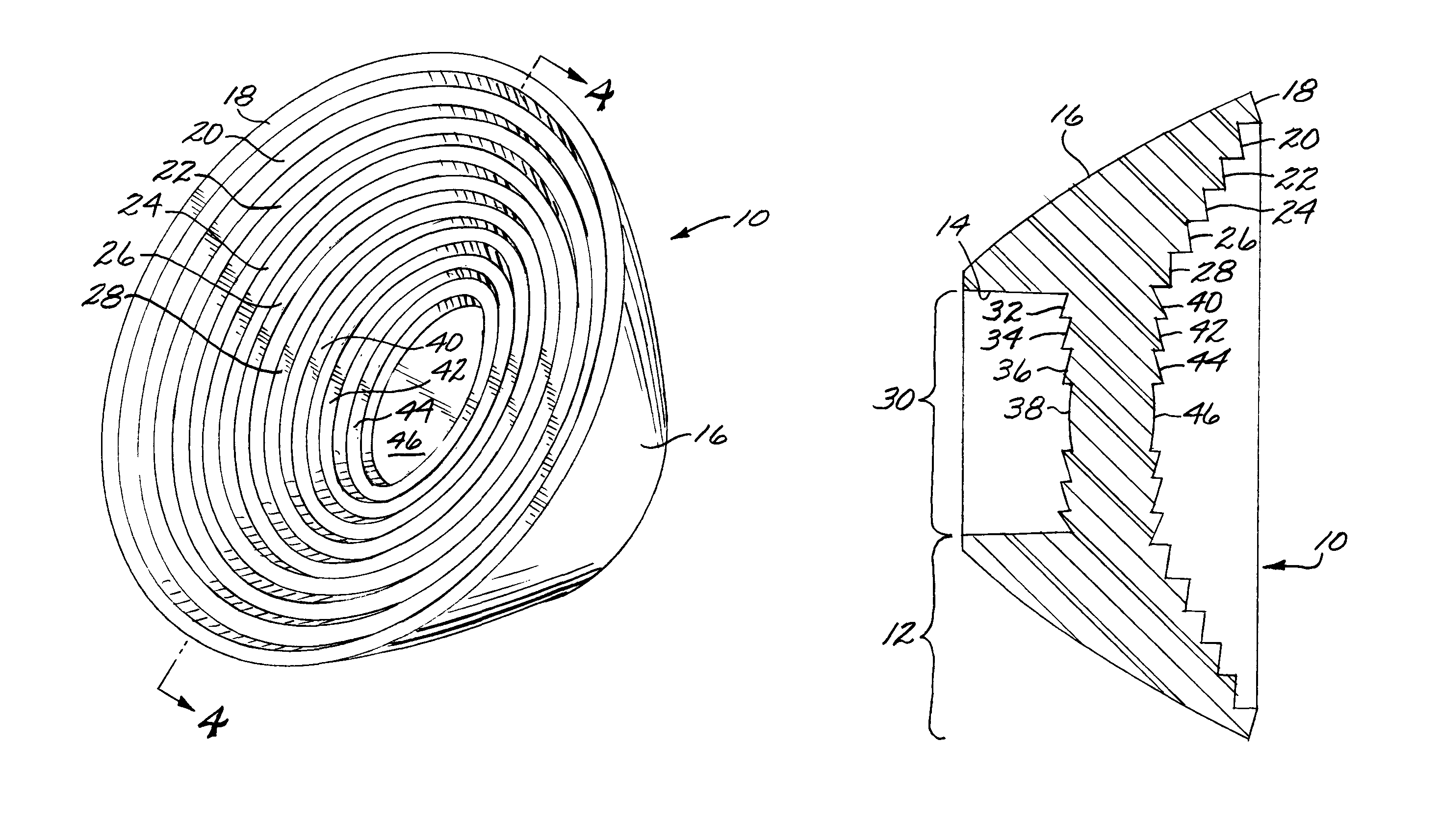
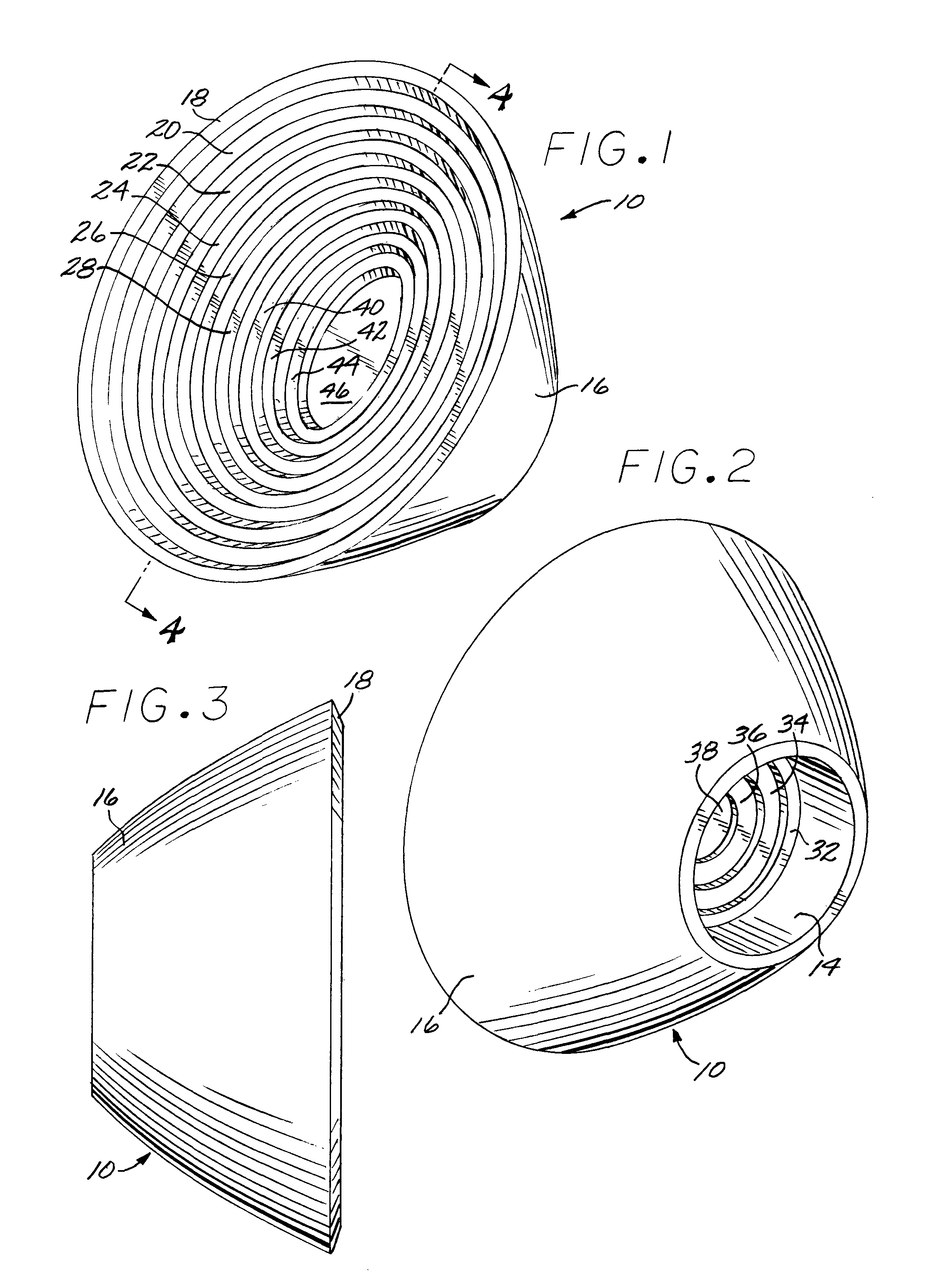
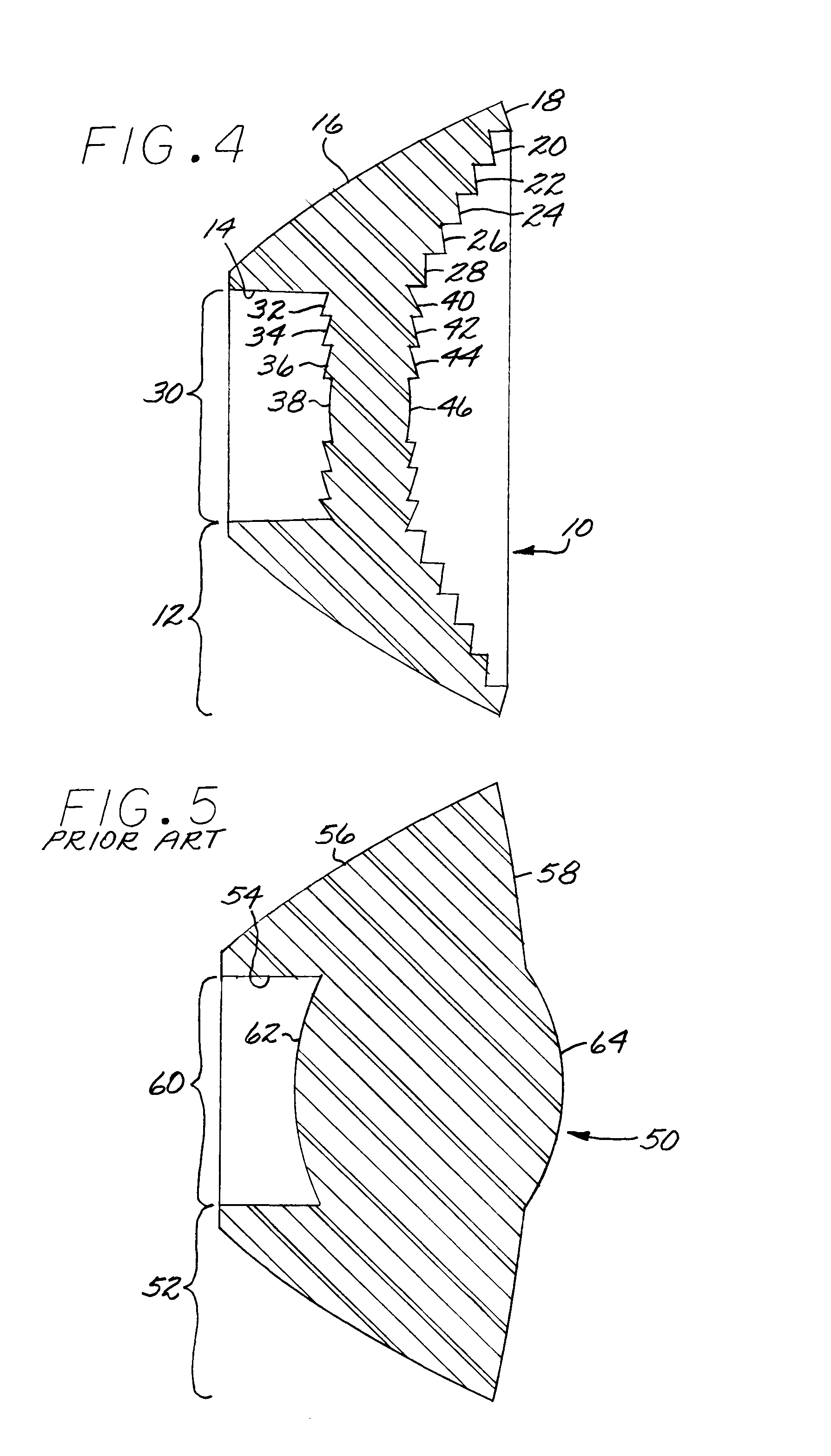
[0028]Although particular embodiments of the invention have been described in detail for purposes of illustration, various modifications may be made without departing from the spirit and scope of the invention. Accordingly, the invention is not to be limited except as by the appended claims. Referring now in greater detail to the various figures of the drawings wherein like reference characters refer to like parts, there is shown in a perspective view at 10 in FIG. 1, a new type of secondary illumination tulip type lens optic having a central lens optic portion and surround total internal reflection (TIR) lens optic portion utilizing refractive faceted optical elements in selected optical surfaces facilitating a thin and low mass design suitable for low cost and high yield manufacturing, particularly suitable for use as a secondary illumination optic for LEDs; however, the device is also suitable for other applications requiring similar optical and manufacturing characteristics.

[002...


PUM


Abstract

A secondary illumination optic, principally directed toward managing light from light emitting diode illumination sources having a primary optical element, is provided comprising a lens combination arranged along the optical axis, a central convex lens portion being centrally positioned on the optical axis, and a surrounding total internal reflection lens portion, with the central optic having a first and incident surface and a second and exiting surface, both comprising refractive faceted optical lens elements, and the total internal reflection optic lens portion having a cylinder shaped aspheric first and incident surface, a second and internal total reflection surface, and a third and exiting surface comprising refractive faceted optic lens elements, wherein, being constructed of resin having optical characteristic, the central and total internal reflection lens portions are molded as an integrated assembly from an optical resin providing a stepped tulip type lens, thinner and higher yielding than prior art lenses.

Description

FIELD OF INVENTION[0001]The present invention generally relates to the field of optical lenses; and, more particularly, to resin based optical elements used for point source light management including secondary illumination lenses utilizing multi-faceted element type optical surfaces.BACKGROUND OF THE INVENTION[0002]Managing the light flux from a light emitting diode (LED) source, typically being a point source, requires the use of a complex optical lens for gathering as much of the light emitted from the source as possible and redirecting the light to a surface to be illuminated in the far field in a predetermined illumination pattern. Maximizing the efficiency of an LED lighting system is measured, in part, by the amount of light successfully captured and usefully redirected by the optics to a far field object. A typical LED source has a primary resin optic molded around and encapsulating the semiconductor such that the light emitted from the source ideally behaves similar to a po...

Claims


Application Information

Patent Timeline
Patent Type & Authority Patents(United States)
IPC IPC(8): G02B9/08F21V5/00
CPCG02B3/08F21V5/04F21V7/0091F21Y2101/02F21Y2115/10
Inventor PITOU, DAVID S
Owner TRIFORMIX
Why Eureka
Try Eureka