Method for internal combustion engine with exhaust recirculation

a technology of internal combustion engine and exhaust, which is applied in the direction of machines/engines, electrical control, mechanical equipment, etc., can solve the problems of loss of efficiency of internal combustion engine and increase fuel consumption, and achieve the effects of increasing temperature, increasing fuel consumption, and maintaining a temperature rang

Active Publication Date: 2011-12-06
VOLVO LASTVAGNAR AB
View PDF12 Cites 4 Cited by
  • Summary
  • Abstract
  • Description
  • Claims
  • Application Information

AI Technical Summary

Benefits of technology

[0003]It is known to supply hydrocarbons to the exhaust gas stream in order to increase the temperature and thereby maintain a temperature range. The drawback with such methods is increased fuel consumption. If the temperature of the exhaust gas stream is low, more hydrocarbons are needed in order to maintain the temperature range. Increased emission control requirements have therefore often resulted in a loss of efficiency of the internal combustion engine. It is therefore important to produce methods which allow effective exhaust emission control without adversely affecting the efficiency of the engine.
[0004]Recirculation of exhaust gases, so-called EGR (Exhaust Gas Recirculation), is a known method in which a part of the total exhaust gas flow of the engine is recirculated and this subflow is fed to the inlet side of the engine, where it is mixed with incoming air for introduction into the cylinders of the engine. It thereby becomes possible to reduce the quantity of nitrogen oxide in the exhaust gases.
[0005]It is desirable to produce a method of using an internal combustion engine with an exhaust gas recirculation system, which method makes it possible to maintain a temperature range in the exhaust gas stream without unnecessary adverse effect upon the efficiency of the engine.

Problems solved by technology

The drawback with such methods is increased fuel consumption.
Increased emission control requirements have therefore often resulted in a loss of efficiency of the internal combustion engine.

Method used


Image

  • Method for internal combustion engine with exhaust recirculation
  • Method for internal combustion engine with exhaust recirculation
  • Method for internal combustion engine with exhaust recirculation

Examples


Embodiment Construction

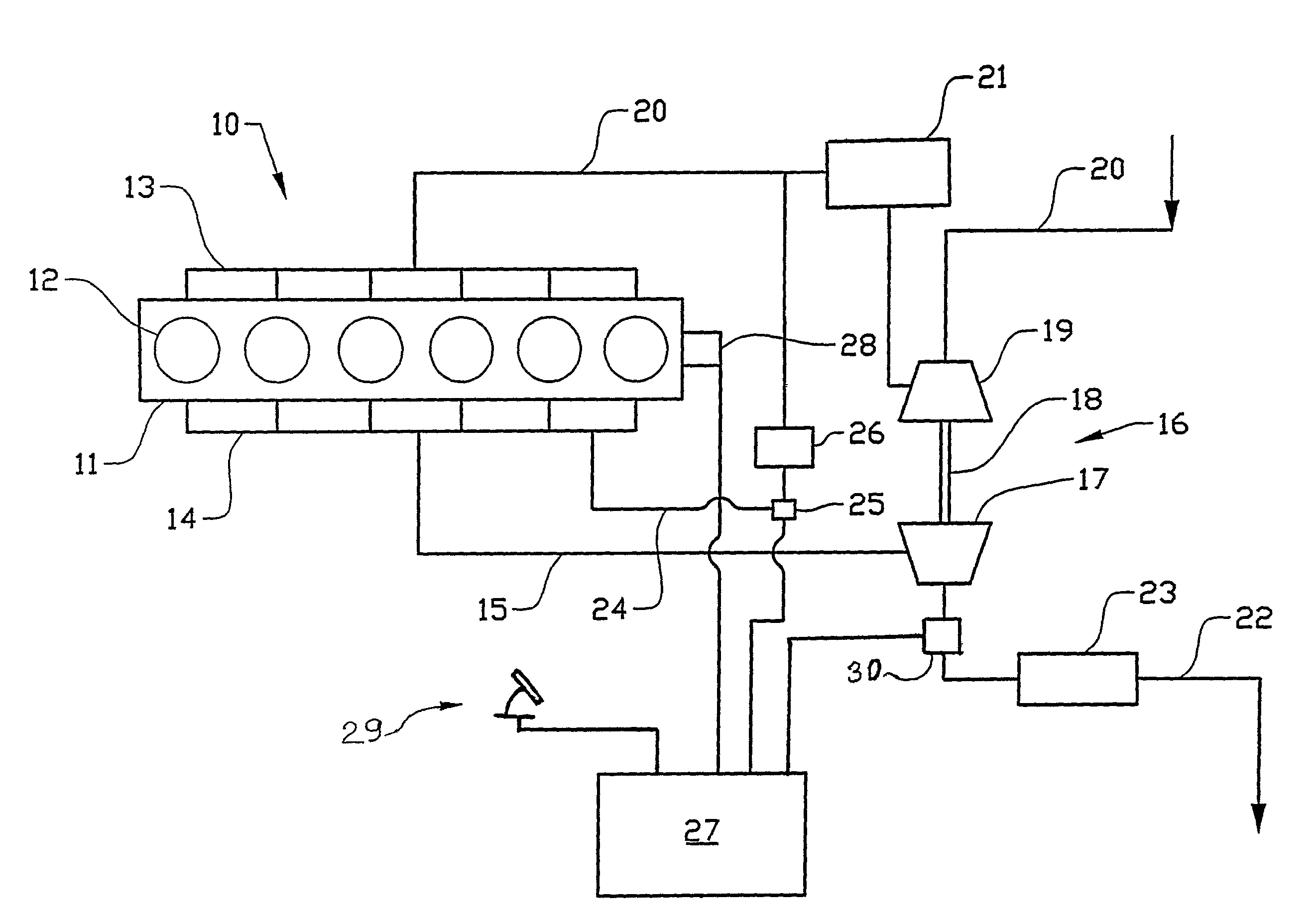
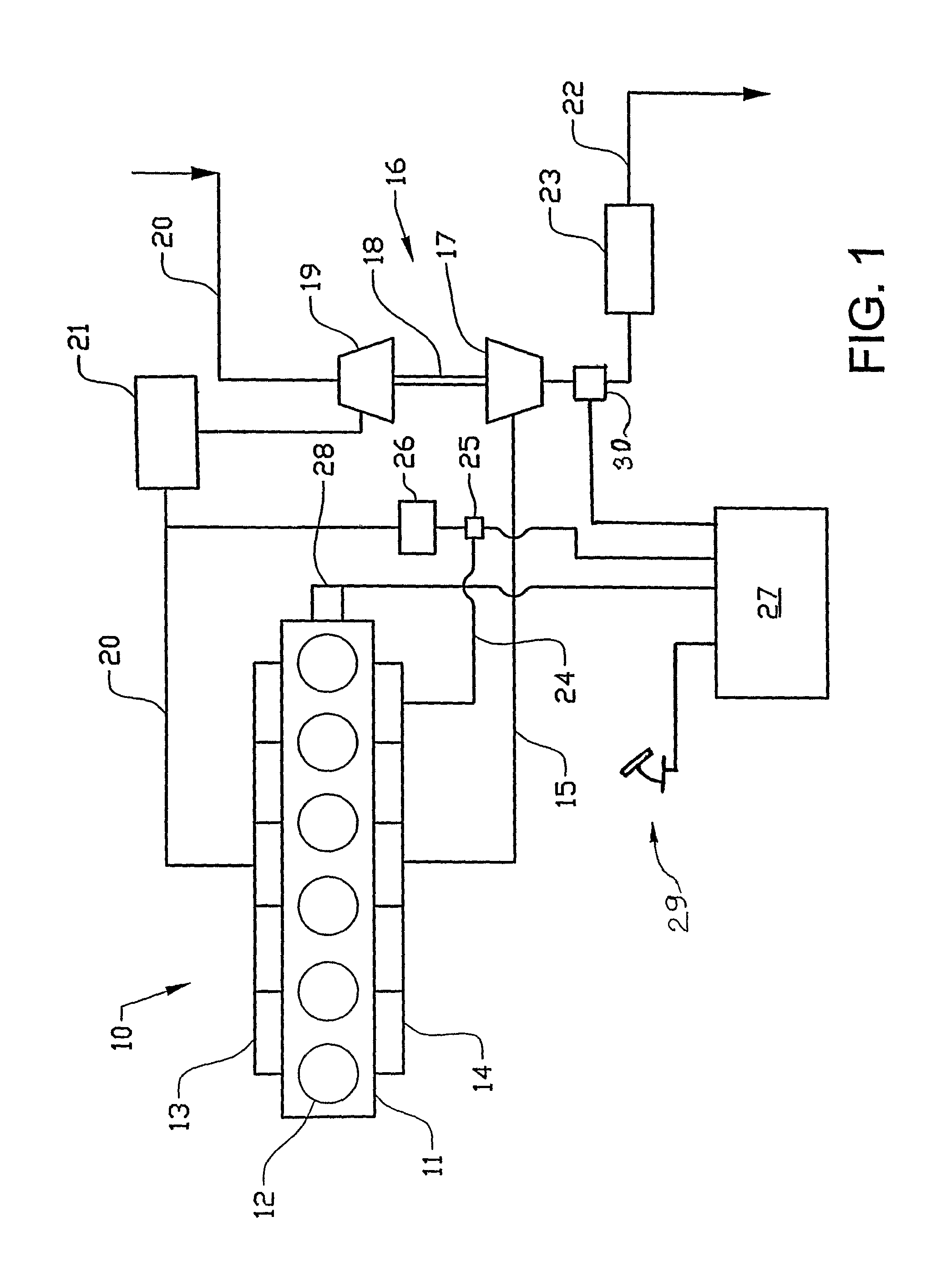
[0011]The internal combustion engine 10 shown in schematic representation in FIG. 1 is used in a vehicle, for example a truck or a bus, and comprises an engine block 11 comprising six piston cylinders 12, with an intake manifold 13 and an exhaust manifold 14. The exhaust gases are led via an exhaust pipe 15 to the turbine wheel 17 of a turbo unit 16. The turbine shaft 18 drives the compressor wheel 19 of the turbo unit, which, via an induction pipe20, compresses incoming air and conveys it via a charge-air cooler 21 to the intake manifold 13.

[0012]Fuel is fed to the respective cylinder 12 via injection devices (not shown).

[0013]Exhaust gases which have passed through the turbocharger 16 are led onward to the atmosphere via the exhaust pipe 22, which leads the exhaust gases through an exhaust aftertreatment device, for example a particle trap or a catalyst 23. For example, regeneration of a particle trap can be achieved by the oxidation of unburnt fuel in a catalyst which is placed u...


PUM


Abstract

A method is provided for maintaining the heat in an exhaust after treatment system connected to the exhaust pipe of an internal combustion engine. The engine is used to propel a vehicle and is equipped with a valve-controlled EGR duct for the adjustable recirculation of exhaust gases from the exhaust side of the engine to its induction side. According to the invention, it is detected that neither the braking system nor the throttle control mechanism of the vehicle is activated and that the vehicle is being driven at a speed in excess of a predetermined value. After this, the gas flow through the EGR duct is regulated so that the gas flow to the exhaust aftertreatment system is reduced to a level which is less than about 50% of the gas flow to the exhaust aftertreatment system with shut-off EGR valve.

Description

BACKGROUND AND SUMMARY[0001]The present invention relates to a method for maintaining the heat in an exhaust aftertreatment system connected to the exhaust pipe of an internal combustion engine, which engine is used to propel a vehicle and is equipped with a valve-controlled EGR duct for adjustable recirculation of exhaust gases from the exhaust side of the engine to its induction side.[0002]In internal combustion engines with exhaust aftertreatment systems, it is desirable for these aftertreatment systems to be able to operate within a favorable temperature range, for example 250-350 degrees Celsius. Sometimes, the operating conditions of an internal combustion engine can be such that the exhaust gas temperature is too low for said temperature range to be able to be maintained. One example of such operating conditions is when the engine is dragging, i.e. a vehicle which is normally driven by the engine is coasting down a hill. In this instance, the engine is in principle pumping fr...

Claims


Application Information

Patent Timeline
Patent Type & Authority Patents(United States)
IPC IPC(8): F02M25/06
CPCF02D41/0055F02M25/0718F02D41/0235F01N3/2053F02B29/0406F02B37/00F02D41/123F02M25/0707F02M25/0727Y02T10/47F02D2200/501F02M26/05F02M26/15F02M26/23Y02T10/40Y02A50/20
Inventor ALM, CHRISTERBERNLER, HANS
Owner VOLVO LASTVAGNAR AB
Why Eureka
Try Eureka