No clog shunt using a compact fluid drag path

a fluid drag path and fluid management technology, applied in the field of medical devices, can solve the problems of increasing pressure on the brain, obstruction of the system, enlargement of the ventricle, etc., and achieve the effect of reducing clogging

Inactive Publication Date: 2012-01-03
NEW JERSEY INSTITUTE OF TECHNOLOGY
View PDF102 Cites 10 Cited by
  • Summary
  • Abstract
  • Description
  • Claims
  • Application Information

AI Technical Summary

Benefits of technology

[0025]A removable sheath that is coated or not coated with a layer to which particulates tend to adhere; the removable sheath is placed on the proximate (or ventricular) end of the shunt tube to be used during insertion. The removable sheath is removed after the disturbance due to insertion settles. This feature will keep the tube clear of obstructions during and immediately after insertion.
[0026]An increased pore opening size. The end of the shunt tube is opened to a standard shunt tube diameter of 1.0 to 1.3 mm, with added holes in the sides of comparable diameter so that particles with smaller diameter can enter without obstruction. The shunt tube is coated with a layer that has a low adhesion for the particulates from the ventricular brain cavity as are most current shunt tubes. The holes in the side of the tube are comparable to the tube diameter. This feature will allow particulates, except unlikely ones with diameters greater than 1.0 mm, to enter the tube, shifting particulate accumulation away from the ventricular region of the shunt which is the least convenient place and where there is no room for a large filter, to an extracranial location.
[0027]The use of a shunt with a shunt tube having a large capacity filter at an extracranial location for hydrocephalus. The filter is designed in the form of a large sheet through which water flows in from below and out above. In a preferred embodiment, the filter pore size is 0.3-0.4 mm diameter, small enough to eliminate particles that would clog other devices, such as pressure and back-flow control and pressure and flow measurement devices. The filter is placed subcutaneously, but at a convenient location for surgical access or is placed partially external to a patient's skin when the shunt is implanted. The filter resides in a housing, so that it may be easily removed without disturbing any other part of the system, especially the tubing that traverses the patient's body and connects to the housing. For instance, in the case of a filter for the eye, the filter may be accessible by raising the eyelid. The key is that the procedure would be much simpler and less prone to infection than a re-implantation of the entire shunt, which is the current standard procedure when a shunt clogs.
[0029]The flow meter and the filter together would allow an indication of partial clogging of the filter and a means of changing the filter just when change is needed.
[0030]It is an object of the invention to provide a shunt that exhibits reduced clogging because the proximal holes would be bigger and the distal holes would be more numerous compared to currently available shunts.
[0039]It is an object of the invention to provide an extracranial filter with a filter component that is removable and replaceable with minimal invasion.

Problems solved by technology

Blockage of the flow of CSF consequently creates an imbalance between the amount of CSF produced by the choroid plexus and the rate at which CSF is absorbed into the bloodstream, thereby increasing pressure on the brain, which causes the ventricles to enlarge.
The most common complication with shunting is obstruction of the system.
Although obstruction or clogging may occur at any point along the shunt system, it most frequently occurs at the ventricular end of the shunt system.
While there are several ways that the ventricular catheter may become blocked or clogged, obstruction is typically caused by growth of tissue, such as the choroid plexus, around the catheter and into the pores.
The pores of the ventricular catheter can also be obstructed by debris, bacteria, or blood clogged in the pores of the catheter.
Additionally, problems with the ventricular catheter can arise from overdrainage of the CSF, which can cause the ventricle walls to collapse upon the catheter and block the pores in the catheter wall, thereby preventing CSF drainage.
This process can be ineffective, however, due to the small size of the pores of the ventricular catheter and due to the small amount of flushing liquid available in the shunt system.
As with the process of backflushing, using a built-in mechanism to flush the shunt system can also fail to remove the obstruction due to factors such as the size of the pores and the degree and extent to which the pores have been clogged.
These repairs, however, may be incapable of removing obstructions from the ventricular catheter depending on the location of the clogged pores.
Additionally, the extent of tissue growth into and around the catheter can also preclude the creation of additional pores, for example, in situations where the tissue growth covers a substantial portion of the ventricular catheter.
Another disadvantage of creating new apertures to repair an occluded ventricular catheter is that this method fails to prevent or reduce the risk of repeated obstructions.
Because attempts at flushing or repairing a blocked ventricular catheter are often futile and ineffective, occlusion is more often treated by replacing the catheter.
Although this can be accomplished by simply removing the obstructed catheter from the ventricle, the growth of the choroid plexus and other tissues around the catheter and into the pores can hinder removal and replacement of the catheter.
Not only do these procedures pose a significant risk of injury to the patient, they can also be very costly, especially when shunt obstruction is a recurring problem.

Method used


Image

  • No clog shunt using a compact fluid drag path
  • No clog shunt using a compact fluid drag path
  • No clog shunt using a compact fluid drag path

Examples


Embodiment Construction

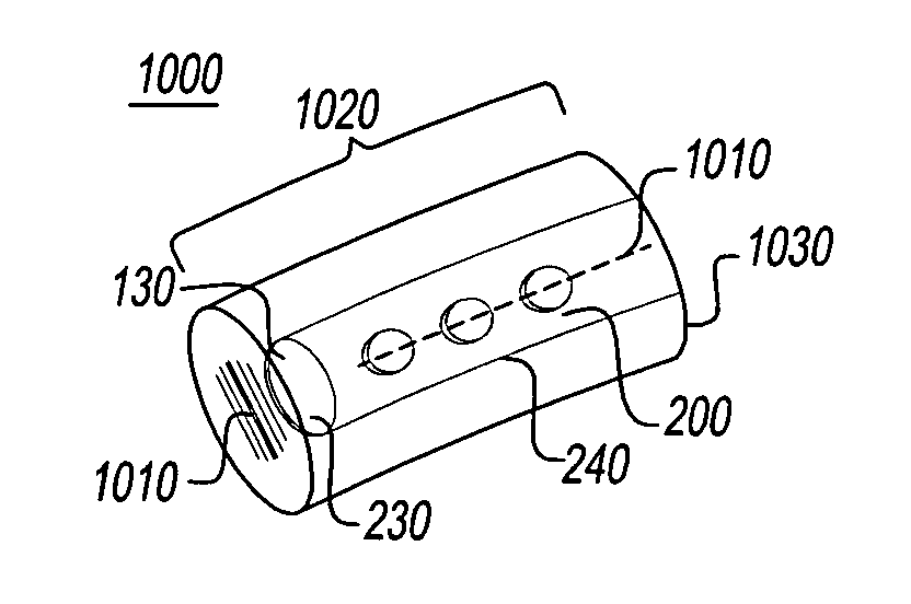
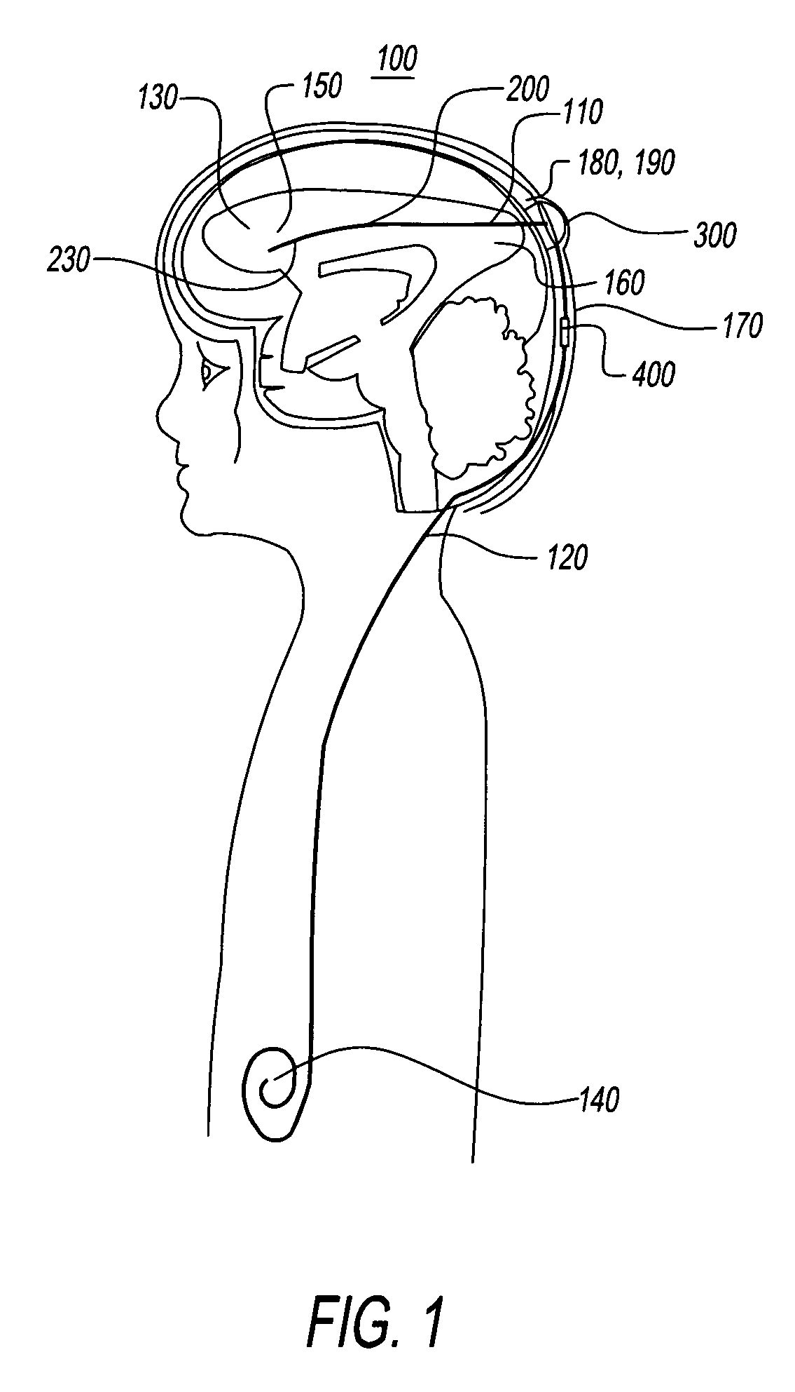
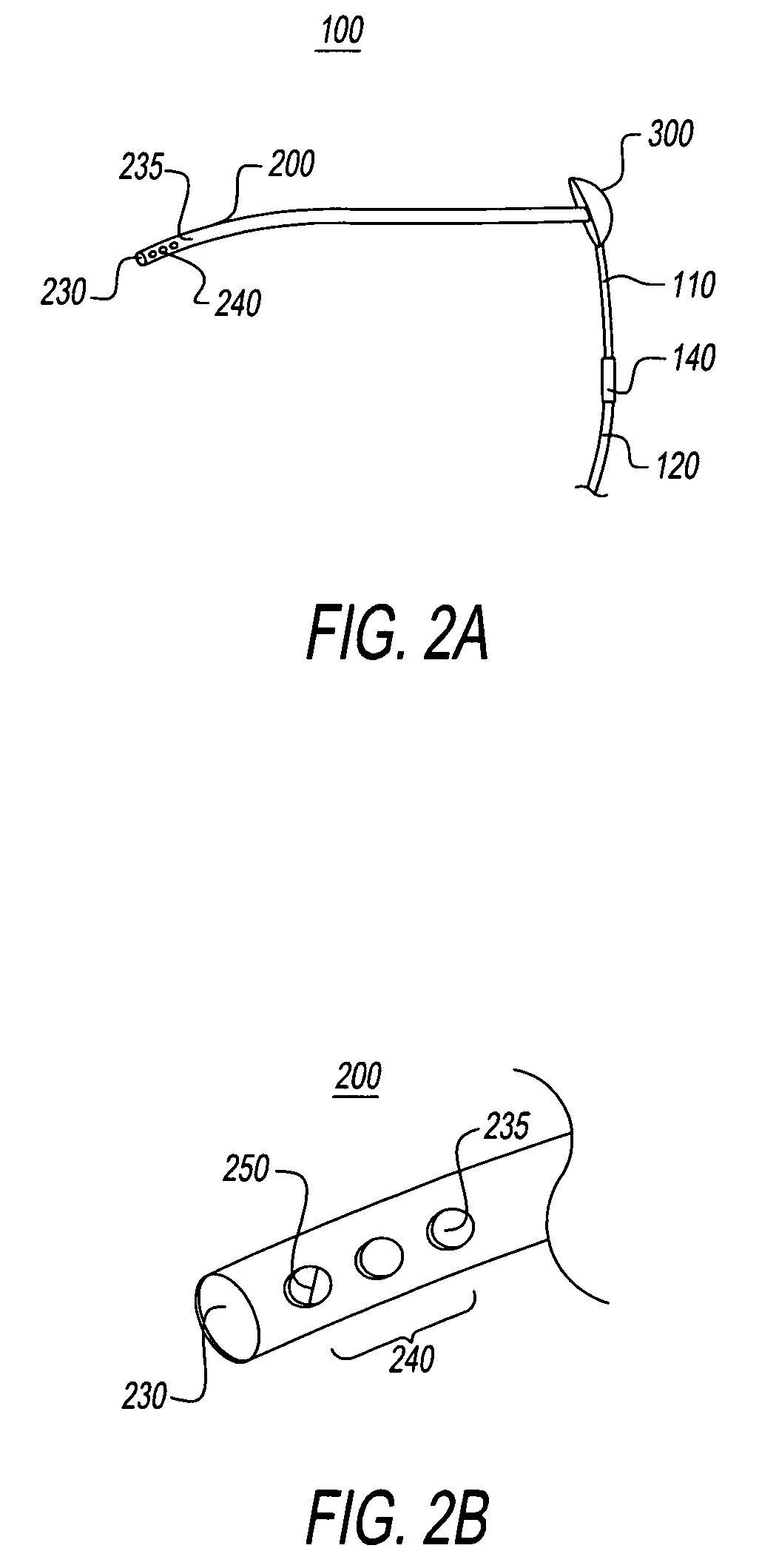
[0054]FIG. 1 shows medical apparatus 100, with shunt 110, shunt tube 120, shunt proximate end 130, shunt distal end 140, organ 150, skull 160, skin 170, extracranial space 180, subcutaneous space 190, catheter 200, catheter tip 230, extracranial filter 300, additional component 400. The organ may be any organ that requires fluid control, but in a preferred embodiment the organ is a brain or an eye, and the fluid being controlled is CSF, or cerebrospinal fluid. The catheter 200 may be a ventricular catheter, and the organ may be a human brain. Alternately, the organ may be a human eye.

[0055]FIG. 1 illustrates how the invention may be used to drain CSF from the brain, and how shunts of the prior art have been improved in this invention. The shunt catheter 200 extends from the organ 150 to the outside of the skull 160, where it enters an extracranial filter 300. The extracranial filter 300 lies just under the skin 170, where it is relatively easy to access. The shunt tube 120 then exte...


PUM


Abstract

The present invention is an improved shunt system for draining CSF. The system includes a removable sheath for reduction of catheter clogging during shunt insertion, a catheter with relatively large holes, an extracranial filter to allow non-invasive filter replacement, and a wireless flow / pressure meter to monitor and control CSF flow.

Description

FIELD OF THE INVENTION[0001]The present invention relates to medical devices, more specifically to a fluid management device or shunt, that minimizes the risk of blockage or obstruction of pores in the catheter and which contains a pressure and flow control meter.BACKGROUND OF THE INVENTION[0002]Hydrocephalus is a neurological condition that is caused by the abnormal accumulation of cerebrospinal fluid (CSF) within the ventricles, or cavities, of the brain. CSF is a clear, colorless fluid that is primarily produced by the choroid plexus and surrounds the brain and spinal cord. CSF constantly circulates through the ventricular system of the brain and is ultimately absorbed into the bloodstream. CSF aids in the protection of the brain and spinal cord. Because CSF keeps the brain and spinal cord buoyant, it acts as a protective cushion or “shock absorber” to prevent injuries to the central nervous system.[0003]Hydrocephalus, which affects children and adults, arises when the normal dra...

Claims


Application Information

Patent Timeline
Patent Type & Authority Patents(United States)
IPC IPC(8): A61M1/00A61M5/00
CPCA61M27/006A61M2027/004A61M2210/0612A61M2210/0693
Inventor THOMAS, GORDON A.FARROW, REGINALD CONWAYLIU, SHENG
Owner NEW JERSEY INSTITUTE OF TECHNOLOGY
Why Eureka
Try Eureka