Method for localizing remote devices, using acoustical and electromagnetic waves

a remote device and electromagnetic wave technology, applied in the direction of gyroscope/turn-sensitive devices, speed measurement using gyroscopic effects, reradiation, etc., can solve the problems of insufficient accurate knowledge of the position of the node, high cost of solution, and significant increase in the energy consumption of each node. , to achieve the effect of high reliability and immunity

Inactive Publication Date: 2012-01-03
CAROTENUTO 50 INTEREST RICCARDO
View PDF20 Cites 32 Cited by
  • Summary
  • Abstract
  • Description
  • Claims
  • Application Information

AI Technical Summary

Benefits of technology

[0009]The object of the present invention is to provide an ingenious algorithm for the determination of the position of remote devices, which is based on the joint use of acoustic and electromagnetic waves, and is characterised by a high reliability and immunity with respect to ambient noise.
[0011]An additional object of the present invention is to provide a method for detecting remote devices by using acoustical and electromagnetic waves, which is based on the use of standard technologies and protocols that are already known in the field of remote detection and of electronic technologies, in order to facilitate maintenance and improve reliability while limiting costs at the same time.
[0014]The method provides analysis means associated with the apparatus, which are capable of processing the measurements related to the distances between the transmitter and each receiver. The analysis means comprise in turn detection means and data processing means. The detection means first produce acoustic pulses whose emission times are detected, and then the respective measurements are performed, relating to the time period between the signal transmission and the reception by the receiver of the corresponding electromagnetic wave. The calculation means are used to process the measurements of the times and therefore of the acquired distances. More specifically, a set of “lighthouses”, or “buoys”, emits a sequence of acoustical pulses or ultrasound pulses inside the space region containing the remote devices, that is, the network elements. At the time each remote device is reached by the acoustical wavefront, it transmits, independently of all other devices, an acknowledge signal to the radio base (or CIP), in the form of a radiofrequency signal (RF) in the free ISM band. The radio base knows the positions of the “lighthouses” and the arrival times of the acknowledge signals, and based on these data it calculate the position of each remote device, using a robust algorithm. The algorithm, taking advantage of the geometrical constraints of the problem, is capable of eliminating false acknowledge signals due to undesired acoustical reflections, to environmental disturbances, or other causes.

Problems solved by technology

However, often a sufficiently accurate knowledge of the node positions is not available.
To this end, each node could be provided with a Global Positioning System (GPS), but this solution would be very expensive and would increase significantly the energy consumption of each node.
Moreover, the spatial resolution provided by the GPS could be insufficient for many applications, like the accurate determination of the position (localization) of objects and persons inside a house.

Method used


Image

  • Method for localizing remote devices, using acoustical and electromagnetic waves
  • Method for localizing remote devices, using acoustical and electromagnetic waves
  • Method for localizing remote devices, using acoustical and electromagnetic waves

Examples


Embodiment Construction

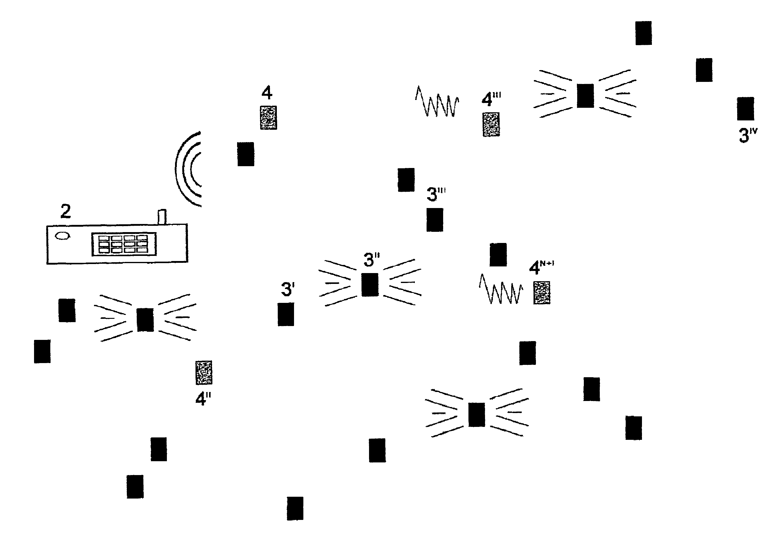
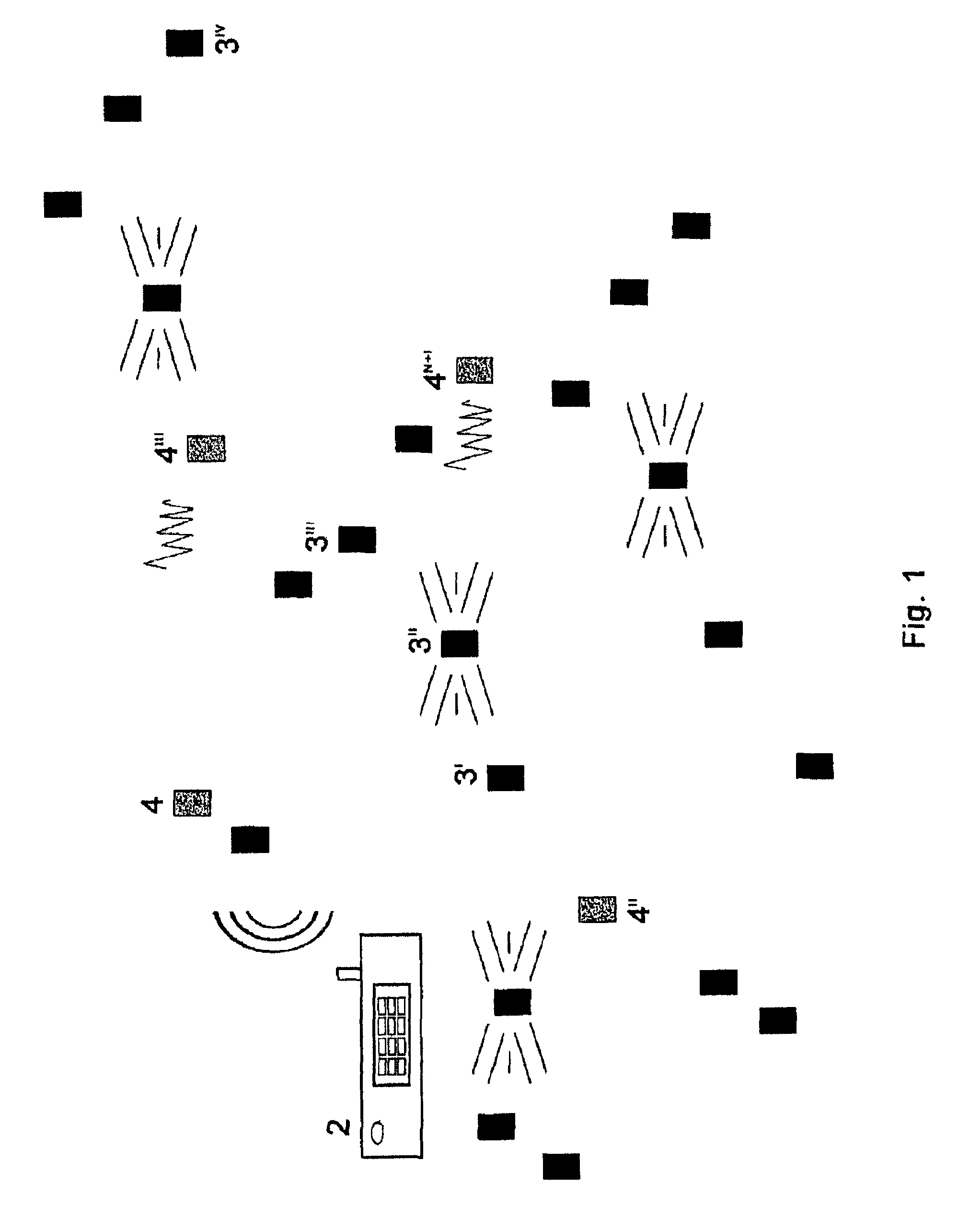
[0016]For the only purpose of more clearly illustrating the invention, but without limiting in this way its applicability and scope, in the following description some specific embodiments will be described by referring to the annexed FIG. 1, the latter showing a schematic representation by functional blocks of the “way of operation” of the present invention.

[0017]The proposed system is based on a network structure in which the whole computational power is concentrated inside the radio base 2 unit, while the localization section for detecting the individual remote devices 3′, 3″, . . . , 3M is extremely simple; in addition, the capability of localizing identical remote devices allows a mass production of remote devices and an enormous reduction of production costs.

[0018]The proposed system can take advantage of the integration on a single chip of: a computing unit with sensors, circuits for conditioning and converting a signal, and a wireless communication electronics, thereby allowi...


PUM


Abstract

Localization of remote devices by: the emission of pulses from acoustic transmitters, whose wavefronts propagate in the space region occupied by the remote devices and finally reach them; the emission of radiofrequency pulses from each remote device at the time of detection of the wavefront by an on-board microphone; the acquisition, by a radio base, of the radiofrequency signals propagating from the remote devices, to evaluate the arrival time delays proportional to the distance between the i-th acoustic source and the j-th remote device; the formation of a reception vector for each emission by the i-th source, this vector having a maximum length M equal to the number of remote devices and consisting of the sequence of distances obtained as the product of the reception times and the estimated sound velocity. These steps are repeated for all acoustic sources, to form N+1 reception vectors, to calculate the position of the device by solving derived matrix equations.

Description

TECHNICAL FIELD[0001]The invention relates in general to a technique—and to the related apparatus—for localizing identical, remote devices. More specifically, it relates to a localization method (position determination method) which uses quick search protocols optimised also under the aspect of noise immunity.BACKGROUND ART[0002]Methods for estimating a distance, normally used for measuring distances in one dimension only, are already known. Some systems were based on ultrasonic methods, which detect the echo of the pulse and utilise highly directional transducers pointing towards the target, in order to measure the position and distance. With such technique, the distance between a transducer and a receiver is indirectly determined by means of the elapsed time, normally called “flight time”, during which the signal generated at the transmitter impinges on the receiver and is reflected back to the transmitter.[0003]Distances are determined by measuring the elapsed time starting from ...

Claims


Application Information

Patent Timeline
Patent Type & Authority Patents(United States)
IPC IPC(8): G01S3/80
CPCG01S5/30G01S11/16
Inventor CAROTENUTO, RICCARDO
Owner CAROTENUTO 50 INTEREST RICCARDO
Why Eureka
Try Eureka