Voltage controlled oscillator having reduced phase noise

a voltage control and phase noise technology, applied in the direction of oscillator, pulse technique, pulse generator, etc., can solve the problems of transistors and other elements introducing a rather significant amount of noise, noise is always present, serious problems in any circuit design, etc., to achieve less time transitioning, improve signal-to-noise ratio, and improve slope

Active Publication Date: 2012-01-24
QUALCOMM INC
View PDF8 Cites 27 Cited by
  • Summary
  • Abstract
  • Description
  • Claims
  • Application Information

AI Technical Summary

Benefits of technology

[0011]Embodiments of the present disclosure pertain to an electronic voltage controlled oscillator. The voltage controlled oscillator has a resonant circuit that causes the output waveform from the voltage controlled oscillator to take on a more squared up shape as compared to that of a conventional sinusoidal waveform. The squared up waveform has a greater slope. Due to this greater slope, active devices spend less time transitioning through the vulnerable zero-crossing points. Consequently, less phase noise occurs during the zero-crossing points. In turn, devices which utilize the present VCO embodiments will have improved signal-to-noise ratios for overall performance gains.

Problems solved by technology

Unfortunately, noise is always present and poses a serious problem to any circuit design.
Unavoidably, the transistors and other elements may introduce a rather significant amount of noise as part of the VCO functionality.
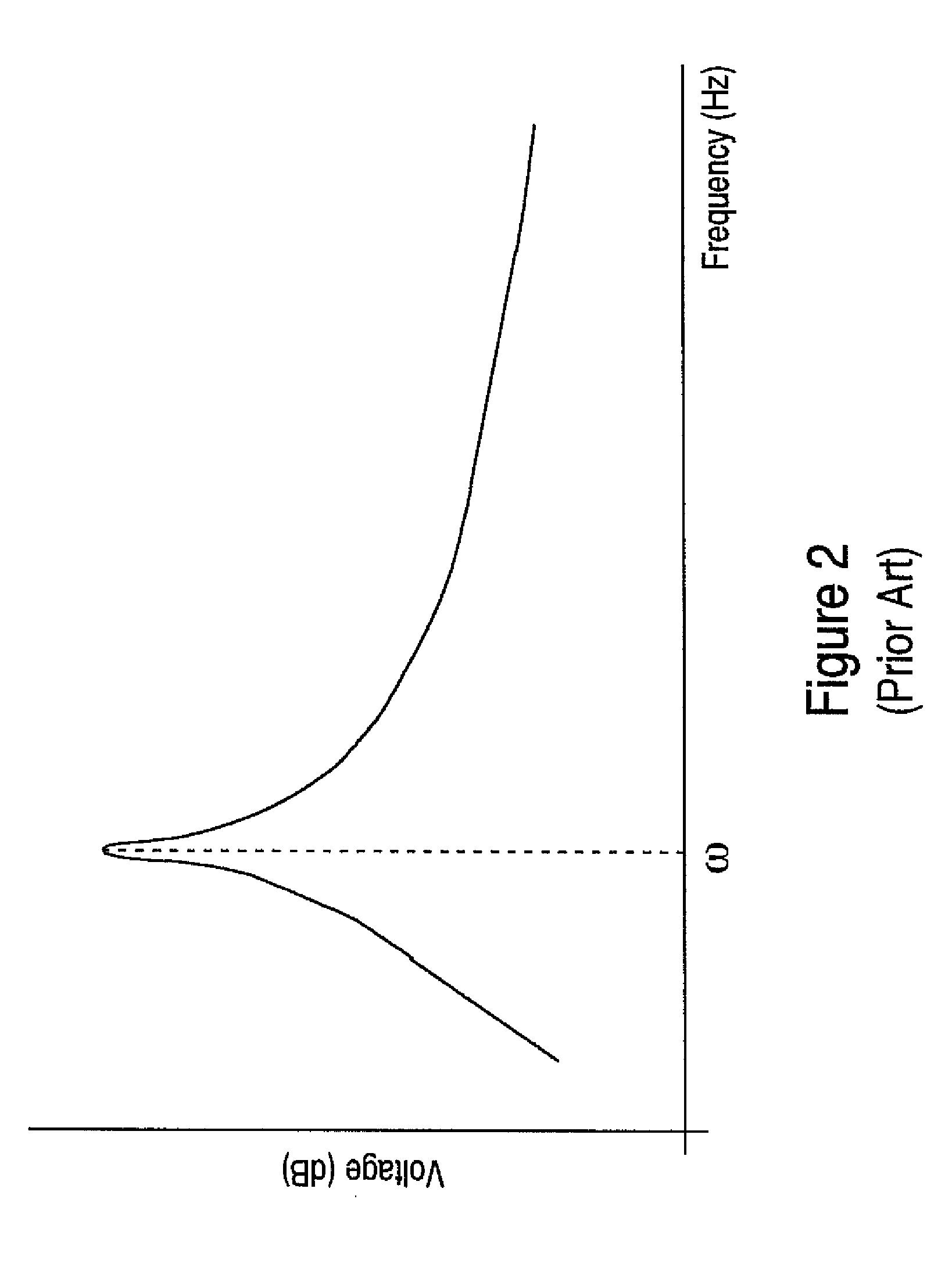
The undesired effect is that individual zero-crossings can deviate from the ideal condition (e.g., the zero crossings may sometimes occur earlier, while at other times, they may occur later than expected).
Phase noise is highly undesirable because it detrimentally impacts the overall performance of the system.
Consequently, the phase noise attributed to the VCO directly reduces the system's signal-to-noise ratio.
However, this solution consumes additional power.
For portable applications (e.g., cell phones), this approach may impose further drains upon battery life.
Furthermore, the additional circuitry adds to the cost of production and may only ameliorate the phase noise by a relatively small margin.
Presently, designers are faced with accommodating the phase noise associated with VCOs and the attendant lower signal-to-noise ratio versus trading off cost / power in terms of adding circuitry to achieve a lower degree of VCO phase noise.

Method used


Image

  • Voltage controlled oscillator having reduced phase noise
  • Voltage controlled oscillator having reduced phase noise
  • Voltage controlled oscillator having reduced phase noise

Examples


Embodiment Construction

[0022]Reference will now be made in detail to several embodiments. While the subject matter will be described in conjunction with the alternative embodiments, it will be understood that they are not intended to limit the claimed subject matter to these embodiments. On the contrary, the claimed subject matter is intended to cover alternative, modifications, and equivalents, which may be included within the spirit and scope of the claimed subject matter as defined by the appended claims.

[0023]Furthermore, in the following detailed description, numerous specific details are set forth in order to provide a thorough understanding of the claimed subject matter. However, it will be recognized by one skilled in the art that embodiments may be practiced without these specific details or with equivalents thereof. In other instances, well-known methods, procedures, components, and circuits have not been described in detail as not to unnecessarily obscure aspects and features of the subject mat...


PUM


Abstract

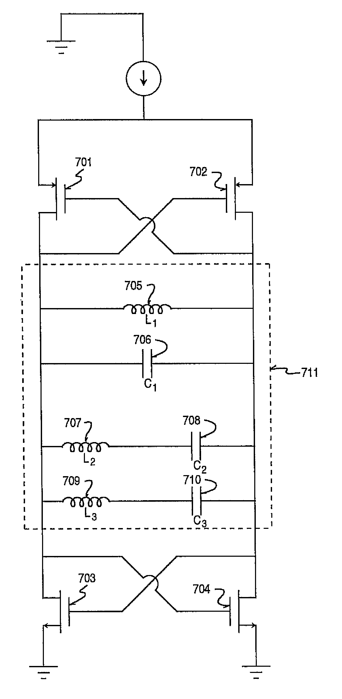
A VCO comprises an LC tank circuit coupled to a plurality of cross-coupled transistor devices. A first resonance frequency of a waveform output of the VCO is dependent upon the values of a first capacitor and a first inductor of the LC tank. The VCO further comprises a first series LC resonator comprising a second capacitor and a second inductor in parallel to the first capacitor and the first inductor. The values of the second capacitor and second inductor are selected to produce a second resonance frequency that is a third harmonic of the first resonance frequency, thereby increasing a slope of the voltage controlled oscillator output. The increased slope reduces phase noise, which leads to improved signal-to-noise ratio.

Description

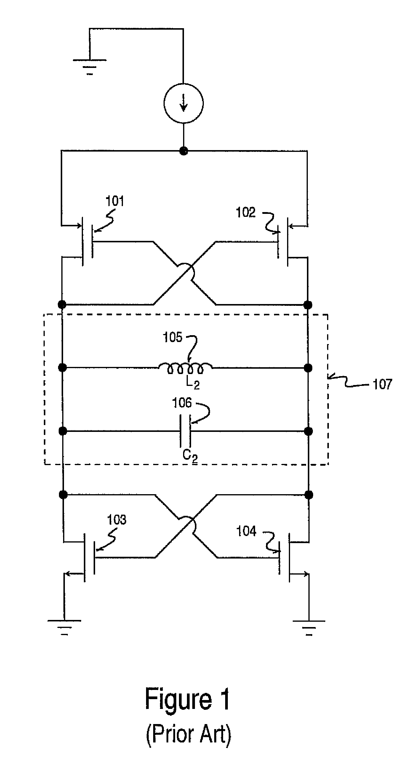
BACKGROUND[0001]1. Field of the Invention[0002]Embodiments of the present invention generally relate to a voltage controlled oscillator having reduced phase noise.[0003]2. Description of the Related Art[0004]A voltage controlled oscillator (VCO) is an electronic circuit that is used to generate an electrical signal that oscillates at a frequency which is controlled by an input voltage. In other words, the input voltage to the VCO sets the frequency of the oscillating VCO output signal. As the input voltage is varied, the VCO's output signal frequency changes in accordance to well-known equations. This VCO voltage-frequency relationship is critical for many different communication applications. Consequently, one or more VCOs are found in virtually every modern communication device, such as in cell phones, radio transmitters and receivers, satellite receivers, GPS systems, wireless data systems, etc.[0005]FIG. 1 shows a circuit diagram of a typical VCO. The VCO includes four transisto...

Claims


Application Information

Patent Timeline
Patent Type & Authority Patents(United States)
IPC IPC(8): H03B5/12
CPCH03B5/1228H03B5/1215
Inventor KACZYNSKI, BRIAN
Owner QUALCOMM INC
Why Eureka
Try Eureka