
Non-contact capacitive datalink for a downhole assembly

a capacitive datalink and assembly technology, applied in the field of downhole tools, can solve the problems of tool failure, tool failure, tool failure, etc., and achieve the effects of low mass, simple and inexpensive manufacturing, and improved shock resistance and vibration resistan

Active Publication Date: 2012-01-24
SCHLUMBERGER TECH CORP
View PDF29 Cites 40 Cited by
  • Summary
  • Abstract
  • Description
  • Claims
  • Application Information

AI Technical Summary

Benefits of technology

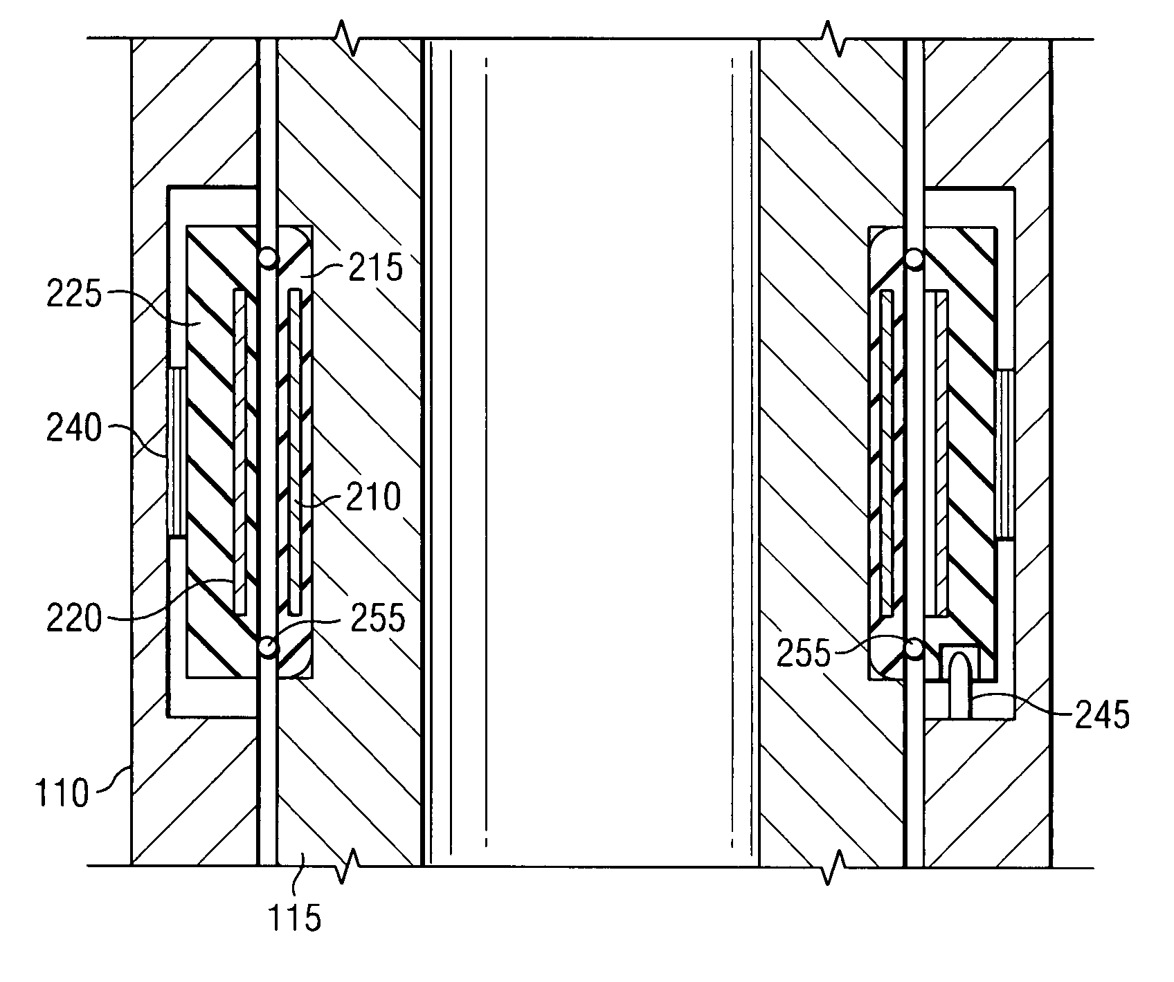
[0010]Exemplary embodiments of the present invention may advantageously provide several technical advantages. For example, exemplary embodiments of this invention provide a non-contact, high-speed data communication channel between first and second members of a downhole assembly. Moreover, exemplary embodiments of the invention also provide for simultaneous non-contact transmission of electrical power between the first and second tool members. Exemplary embodiments of the invention also tend to be relatively simple and inexpensive to manufacture as compared to inductive couplings of the prior art. Exemplary capacitive coupling embodiments also tend to advantageously be low mass and more resistant to shock and vibration than prior art slip ring and inductive coupling devices. In one exemplary embodiment, a capacitive coupling device in accordance with the invention may be advantageously configured to transmit high-speed data signals through an electrical generator (alternator).

Problems solved by technology

While slip rings are known to be commercially serviceable, failure of certain slip ring components is a known cause of downhole tool failure.
For example, slip ring seals have been known to fail, which can result in a loss of communication with the tool and the need to trip out of the borehole.
Loss of electrical contact between the slip ring contact members is also a known cause of tool failure.
For example, inductive couplings tend to occupy a large physical space and are typically expensive to fabricate (due to the use of a wound magnetic core).
Inductive couplings also tend to exhibit low transmission efficiencies owing to the relatively large gap between transmitter and receiver.

Method used


Image

  • Non-contact capacitive datalink for a downhole assembly
  • Non-contact capacitive datalink for a downhole assembly
  • Non-contact capacitive datalink for a downhole assembly

Examples


Embodiment Construction

[0022]Referring first to FIGS. 1 through 7, it will be understood that features or aspects of the embodiments illustrated may be shown from various views. Where such features or aspects are common to particular views, they are labeled using the same reference numeral. Thus, a feature or aspect labeled with a particular reference numeral on one view in FIGS. 1 through 7 may be described herein with respect to that reference numeral shown on other views.

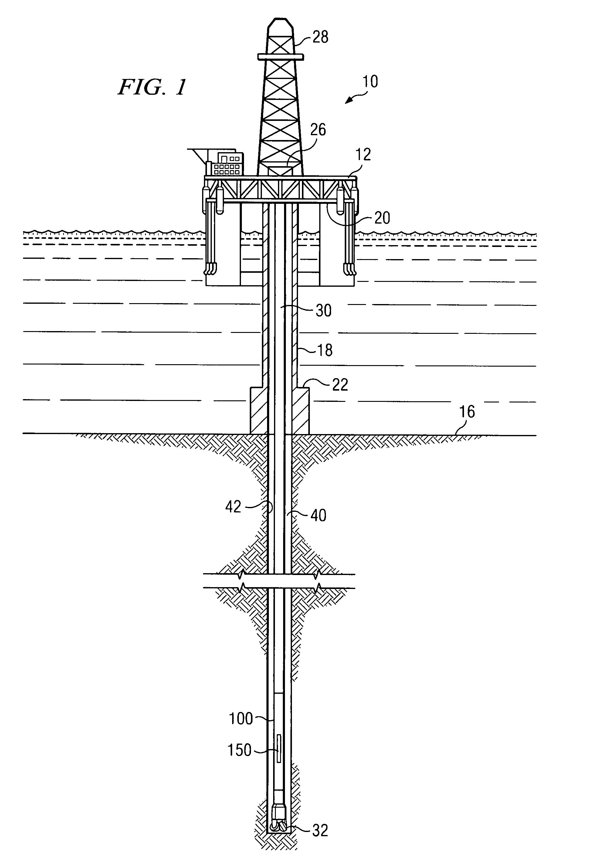
[0023]FIG. 1 illustrates a drilling rig 10 suitable for utilizing exemplary downhole drilling assembly (including steering tool and mud motor) and method embodiments of the present invention. In the exemplary embodiment shown on FIG. 1, a semisubmersible drilling platform 12 is positioned over an oil or gas formation (not shown) disposed below the sea floor 16. A subsea conduit 18 extends from deck 20 of platform 12 to a wellhead installation 22. The platform may include a derrick 26 and a hoisting apparatus 28 for raising and lowering...


PUM


Abstract

Aspects of this invention include a downhole assembly having a non-contact, capacitive coupling including first and second transceivers deployed in corresponding first and second downhole tool members. The capacitive coupling is disposed to transfer electrical signals between the first and second transceivers. In one exemplary embodiment, the capacitive coupling is configured to transfer data and power between a substantially non-rotating tool member and a rotating tool member, for example, the shaft and blade housing in a steering tool. Exemplary embodiments of this invention provide a non-contact, high-speed data communication channel between first and second members of a downhole assembly. Moreover, exemplary embodiments of the invention also provide for simultaneous non-contact transmission of electrical power between the first and second tool members.

Description

RELATED APPLICATIONS[0001]None.FIELD OF THE INVENTION[0002]The present invention relates generally to downhole tools, for example, including directional drilling tools such as a steering tool and a mud motor. More particularly, embodiments of this invention relate to a downhole assembly including a non-contact, capacitive coupling apparatus for transmitting electrical power and / or data between first and second members of the assembly.BACKGROUND OF THE INVENTION[0003]As is well-known in the industry, hydrocarbons are recovered from subterranean reservoirs by drilling a borehole (wellbore) into the reservoir. Such boreholes are commonly drilled using a rotating drill bit attached to the bottom of a drilling assembly (which is commonly referred to in the art as a bottom hole assembly or a BHA). The drilling assembly is commonly connected to the lower end of a drill string including a long string of sections (joints) of drill pipe that are connected end-to-end via threaded pipe connecti...

Claims


Application Information

Patent Timeline
Patent Type & Authority Patents(United States)
IPC IPC(8): G01V3/00
CPCG01V11/002E21B17/028
Inventor SUGIURA, JUNICHI
Owner SCHLUMBERGER TECH CORP
Learn More