Respiratory nasal filter

a technology for respirators and filters, applied in respirators, treatment rooms, transportation and packaging, etc., can solve the problems of cumbersome and invasive removal of filters from wearers' faces, reducing the usability of filters, and filter wear is quite noticeable when worn, so as to reduce the inhalation of second hand smoke, and be convenient to carry.

Active Publication Date: 2012-02-07
MOORE JOSEPH K
View PDF18 Cites 7 Cited by
  • Summary
  • Abstract
  • Description
  • Claims
  • Application Information

AI Technical Summary

Benefits of technology

[0016]The filter is ideal for use in the medical, industrial, pharmaceutical and environmental fields in addition to being ideal for use by the general public, particularly those with asthma and / or allergies to everyday exposure of daily contaminants. Additionally, the filter greatly reduces the inhalation of second hand smoke which has been proven to cause disease at any level.
[0017]The filter of the present invention is lighter weight and achieves much greater tolerability than prior art nasal filters, while only using as little as 1 / 10th of the materials needed with prior art filters. The filter, utilizing a smaller filter media than prior art filters, allows the filter to be placed closer to the nasal passage, without actually being inserted into the nasal passage. As discussed at length herein, this results in the filter being less visible or noticeable when worn.
[0018]The close proximity of the filter to the nasal passage also allows back pressure from a user's exhalation to clean the filter mechanism. Further, because the filter is designed to be worn on an individual nostril, the filter can create an inner and outer seal for greater effectiveness in excluding pollutants and contaminants from the user's respiratory system, while only covering approximately 1 / 16th of an inch of skin per nasal passage.
[0019]Additionally, due to the small size of the nasal filters, the filters are extremely lightweight, leading to make the filter unnoticeable to the user when wearing the filter. Similarly, this small size allows for construction of the nasal filter utilizing less filter material than has been required by other nasal filters. Similarly, the thin nonvisible self-sealing outer ring of the nasal filter disclosed herein allows for individually sealing the nasal cavity off without insertion of a nasal filter or other additional discomfort.
[0020]The filter's small and novel design also overcomes the prior art's requirement that the filter be visible when worn. The design is not only small, which necessarily reduces its visibility, but also relies upon clear adhesives and skin colored filters thus minimizing any visibility of the filter.

Problems solved by technology

However, because the filter fits over both nostrils and is tabbed, the filter is quite noticeable when worn.
Additionally, because the proximal tab is generally rectangular in shape to connect the triangular shape of the filter to the skin found at the junction of the face with the bottom of the nose, this creates difficulty and discomfort in removing the filter from a wearer's face as the filter pulls unnecessarily on facial hair in this region.
The approach of the '798 patent is also cumbersome and invasive reducing the usability of the filter.
Such a filter device is cumbersome, heavy and quite noticeable externally.
This nasal glove is cumbersome and externally visible when worn.
As with the previously mentioned patents, this nasal glove covers both nostrils at the same time, adding to its cumbersome nature.
Such an approach not only subjects the nasal insert to additional contamination, but also crushes nasal hairs within the nostril.

Method used


Image

  • Respiratory nasal filter
  • Respiratory nasal filter
  • Respiratory nasal filter

Examples


first embodiment

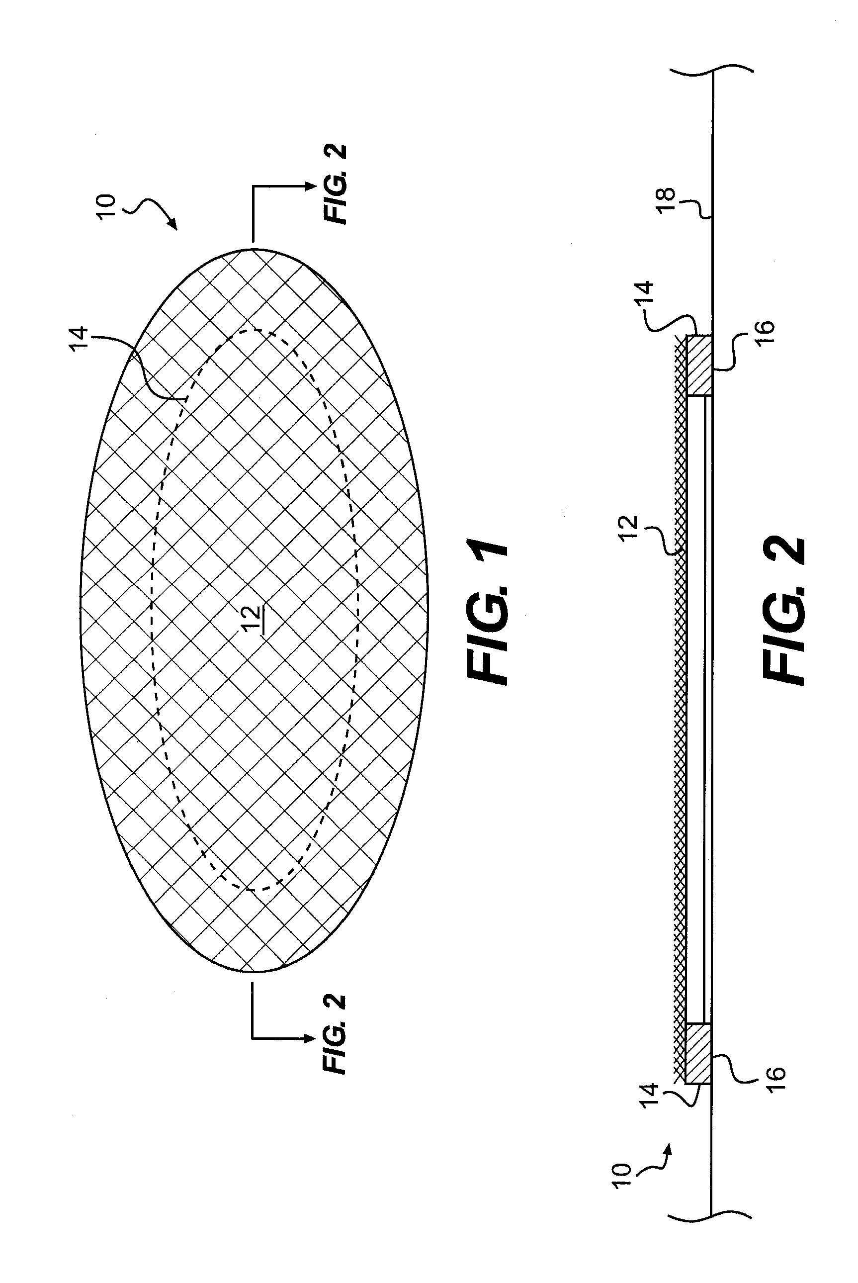
[0035]As shown in FIG. 1, the nasal filter 10 of the invention comprises a generally oval-shaped configuration dimensioned to be slightly larger than the usual size of the periphery of a person's nasal orifice, namely a person's nostril. As best shown in FIG. 2, the nasal filter 10 comprises a filter layer 12 composed of a microporous filter material. The microporous filter material of the filter layer 12 preferably is composed of a moisture resistant filter material with sufficient pore size to filter out the unwanted particulate, bacteria or virus.

[0036]The microporous filter is preferably a spunlaced polyester fabric. This spunlaced fabric is nonwoven. A preferred nonwoven fabric is the PS-1025 provided by Polymer Science, Inc., the technical disclosure of which is hereby incorporated by reference. The PS-1025 is a ¾ ounce beige colored apertured spunlaced polyester fabric, with a total thickness of 0.003 inches. As would be appreciated by a personal skilled in the art, various c...

second embodiment

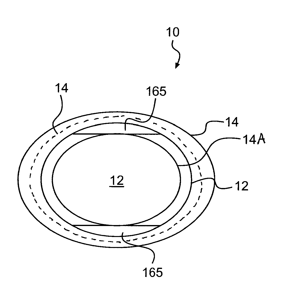
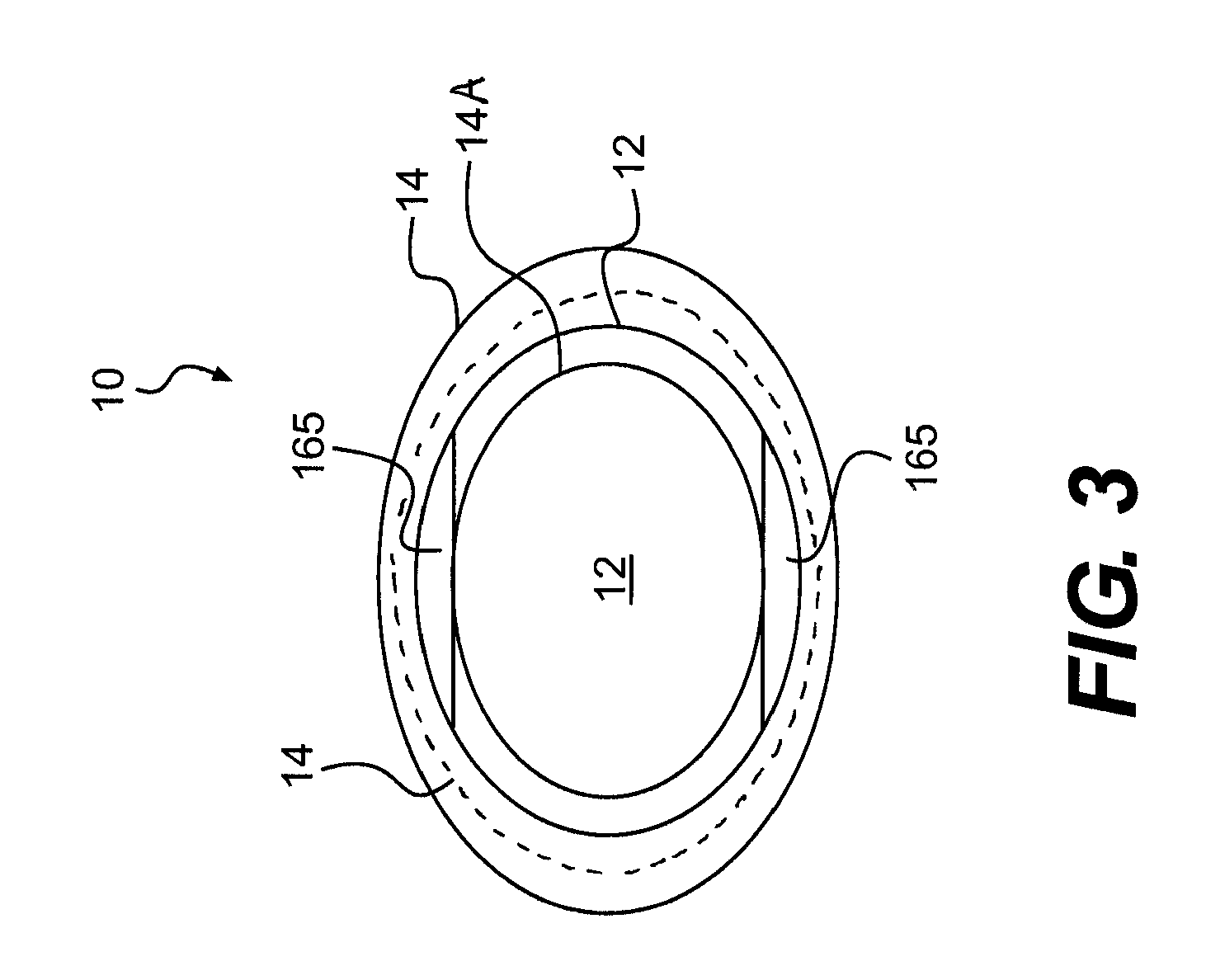
[0043]Referring now to FIGS. 3-5, the respiratory nasal filter 10 of the invention comprises a clear, oval ring-shaped base layer 14 with the adhesive 16 applied to the underside of the base layer 14. The filter layer 12 is formed in a smaller size relative to the clear base layer 14 and is affixed to the underside of the base layer 14. The base layer 14 therefore slightly overlaps the peripheral edge of the filter layer 12 such that the filter layer 12 is adhered to its underside by the adhesive 16. However, the size of the base layer 14 is sufficiently large to define an adhesive area 14A on the base layer 14 beyond the periphery of the filter layer 12. The adhesive 16 thus functions to permanently adhere the filter layer 12 to its underside while also providing adhesive area 14A that removably adheres to the person's skin about the periphery of the person's nostrils.

[0044]It is noted that additional adhesiveness may be provided to the adhesive area 14A. More specifically, a stron...


PUM

PropertyMeasurementUnit
total thicknessaaaaaaaaaa
inner diameteraaaaaaaaaa

Abstract

A respiratory nasal filter including an outer ring having concentric outer periphery and inner periphery sized to the periphery of a user's nasal orifice, a filter layer having an outer periphery larger than the inner periphery of the outer ring, but smaller than the outer periphery of the outer ring and an adhesive applied to the outer ring for bonding the filter layer concentrically to the outer ring and for bonding the outer ring to the columella, a nasal sill, an alar sidewall and the facet of the user's nose.

Description

CROSS-REFERENCE TO RELATED APPLICATION[0001]This application claims the benefit of U.S. Provisional Application No. 60 / 855,711, filed Oct. 31, 2006, the disclosure of which is hereby incorporated by reference herein.BACKGROUND OF THE INVENTION[0002]1. Field of the Invention[0003]This invention relates to a respiratory filter for use by an individual to assist in filtering pollutants.[0004]2. Description of the Background Art[0005]Presently, there exists a need to filter contaminants, pollutants, and other environmental elements from entering a person's nasal passages. U.S. Pat. No. 5,392,773, the disclosure of which is incorporated by reference herein, discloses a respiratory particulate nasal filter with a fine mesh filtering material that is intended to be removably adhered to the lower surfaces of a person's nose to fully cover both of the person's nostrils. The adhesive section has distal, medial, and proximal adhesive tabs which secure and seal the filter while leaving the uppe...

Claims


Application Information

Patent Timeline
Patent Type & Authority Patents(United States)
IPC IPC(8): B29C65/00A62B7/10B32B9/00B32B33/00B32B38/04B32B37/00
CPCA62B23/06A62B7/10Y10T428/1495Y10T428/14Y10T156/1062Y10T156/108Y10T156/1075Y10T428/249953
Inventor MOORE, JOSEPH K.
Owner MOORE JOSEPH K
Why Eureka
Try Eureka