Semiconductor light-emitting element and method for fabrication the same

a technology of semiconductors and light-emitting elements, which is applied in the direction of semiconductor devices, lasers, semiconductor lasers, etc., can solve the problems of unobtainable desired luminous efficiency and still left, and achieve excellent luminous efficiency, increase the effect of the present invention, and reduce thermal damage on the active layer

Active Publication Date: 2012-02-28
ROHM CO LTD
View PDF13 Cites 2 Cited by
  • Summary
  • Abstract
  • Description
  • Claims
  • Application Information

AI Technical Summary

Benefits of technology

[0008]On the other hand, the inventors of this application have proposed a semiconductor laser constituted of a group III nitride semiconductor multilayer structure having a major growth surface defined by a nonpolar plane such as an m-plane in precedently submitted Japanese Patent Application No. 2007-040074. A semiconductor laser having excellent luminous efficiency and a low threshold can be implemented according to the structure.
[0028]The group III nitride semiconductor single-crystalline substrate is preferably a GaN substrate. By using such a GaN substrate, the group III nitride semiconductor multilayer structure becomes a high-quality crystal having a small number of defects. Thus, a semiconductor light-emitting element of higher performance can be implemented.

Problems solved by technology

However, the growth temperature for the p-type layer grown after the active layer is about 1000° C. Therefore, the active layer is thermally damaged due to the temperature for growing the p-type layer, and hence desired luminous efficiency cannot be obtained.
In the semiconductor laser, however, a problem similar to that in the aforementioned case arises when it is attempted to implement light emission in the long wave range of not less than 450 nm.
In order to implement a semiconductor laser excellent in oscillation efficiency in the long wave range, therefore, problems have still been left.

Method used


Image

  • Semiconductor light-emitting element and method for fabrication the same
  • Semiconductor light-emitting element and method for fabrication the same
  • Semiconductor light-emitting element and method for fabrication the same

Examples


second embodiment

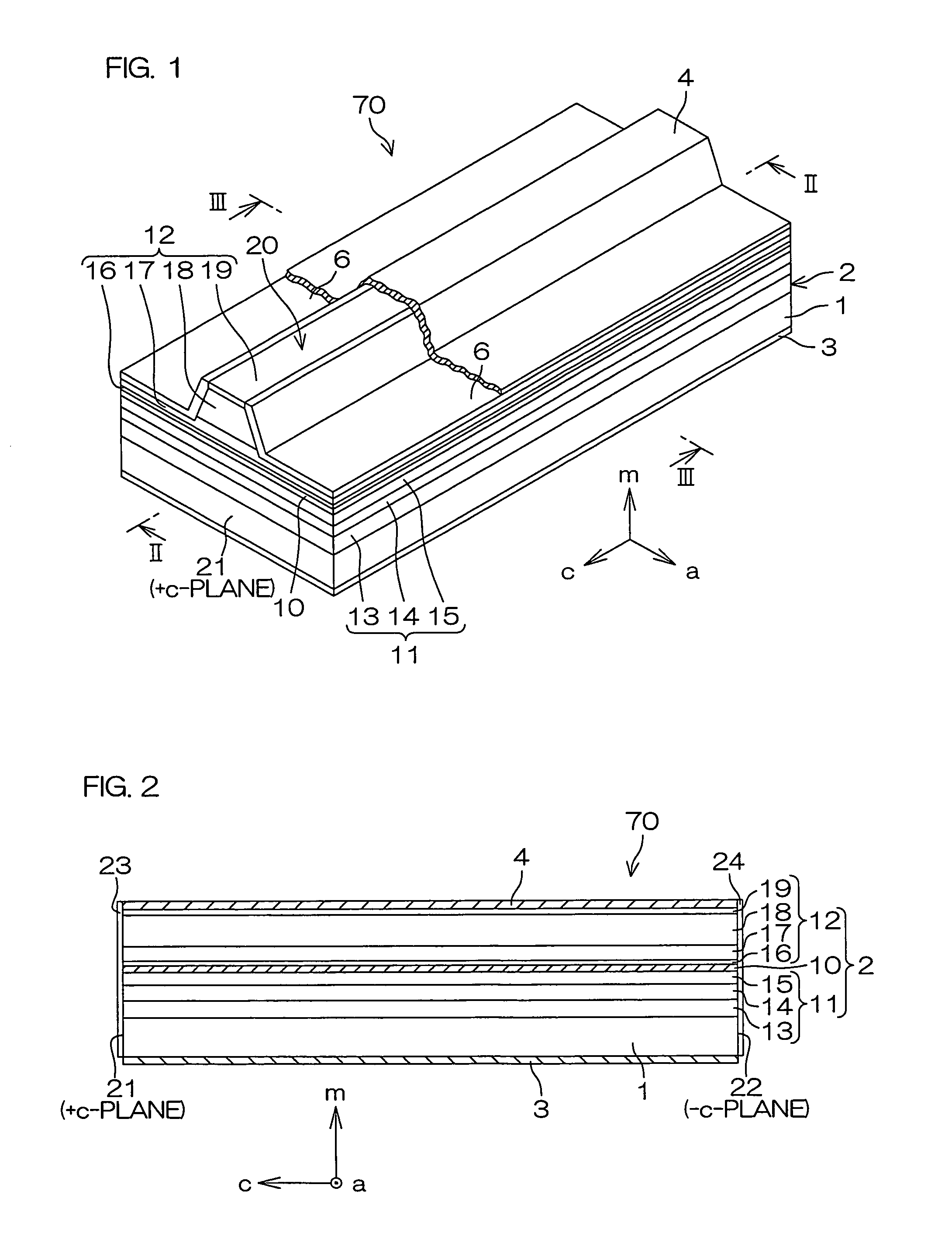
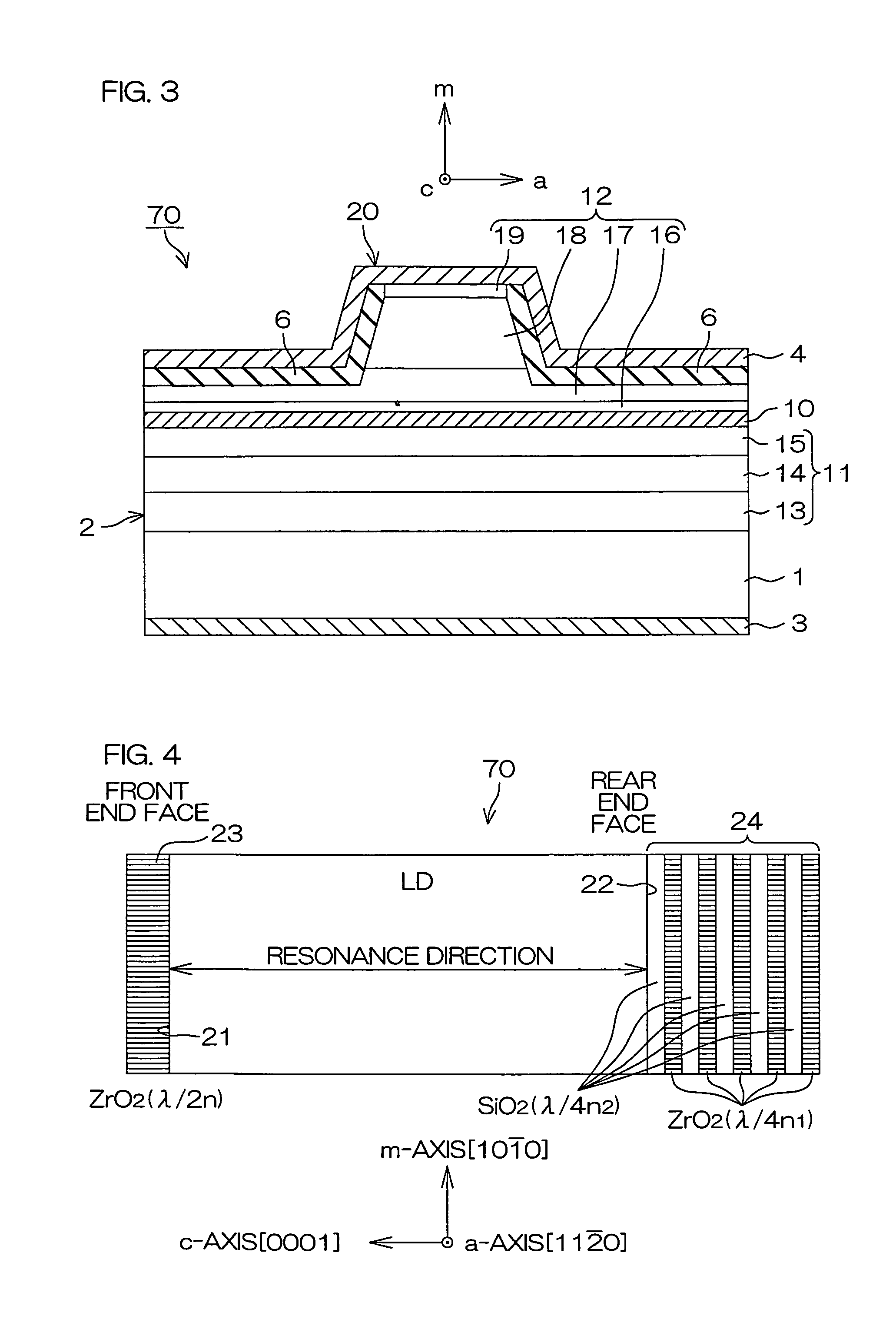
[0099]FIG. 9 is a perspective view showing the structure of a semiconductor laser diode according to the present invention, and FIG. 10 is a longitudinal sectional view along a line X-X in FIG. 9. Referring to FIGS. 9 and 10, portions corresponding to the respective portions shown in the aforementioned FIGS. 1 to 3 are denoted by the same reference numerals.

[0100]In a semiconductor laser diode 80 according to this embodiment, a ridge stripe 20 is formed parallelly to an a-axis direction, and hence both of cavity end faces 21 and 22 are defined by a-planes. The cavity end faces 21 and 22 are also defined by cleavage planes formed by cleavage.

first embodiment

[0101]Stacking faults resulting from epitaxy of a group III nitride semiconductor multilayer structure 2 are formed parallelly to a c-plane. In the structure of the aforementioned first embodiment, therefore, it follows that stacking faults and the waveguide intersect with one another. According to this embodiment, on the other hand, a stripe direction is rendered parallelized town a-axis, and hence a waveguide is parallel to the a-axis. The a-axis is parallel to a c-plane, whereby stacking faults formed parallelly to the c-plane do not intersect with the waveguide. Thus, disturbance of a light guide and increase in a leakage current resulting from stacking faults can be avoided.

third embodiment

[0102]FIG. 11 is a perspective view for illustrating the structure of a semiconductor laser diode according to the present invention. Referring to FIG. 11, portions corresponding to the respective portions shown in the aforementioned FIG. 1 are denoted by the same reference numerals.

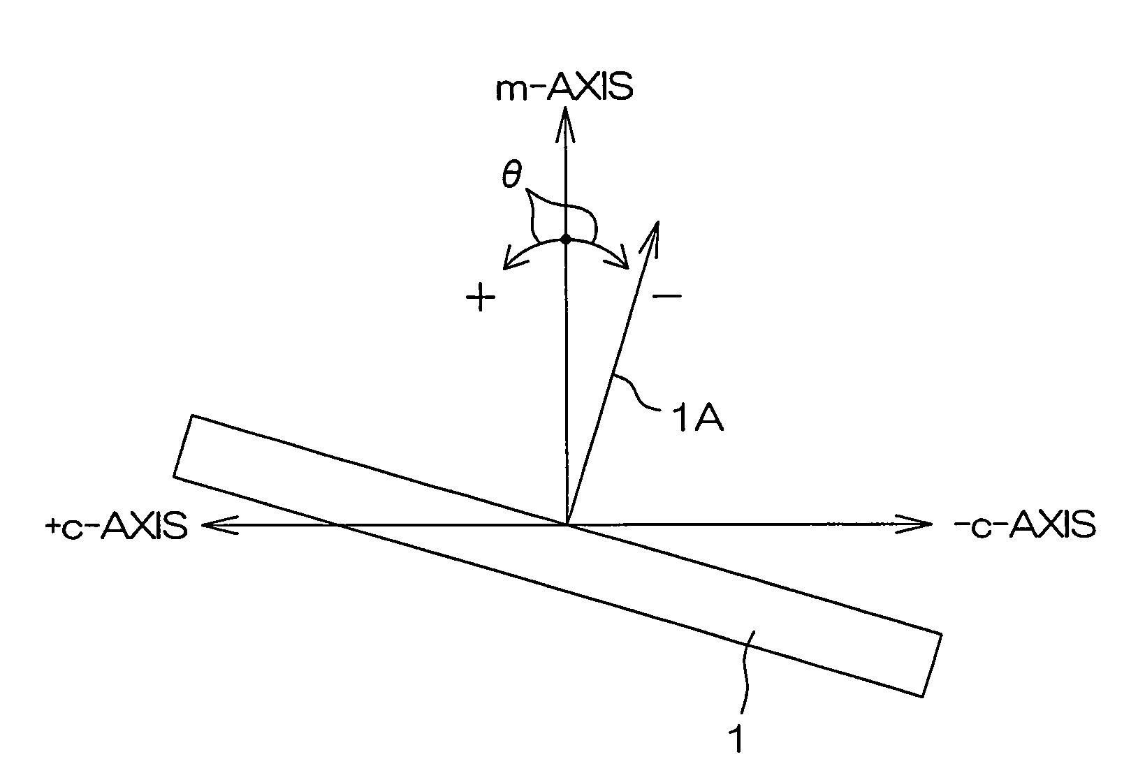
[0103]In a semiconductor laser diode 90 according to this embodiment, a layer containing In including biaxial stress, i.e., an n-type InGaN Layer 26 (having a thickness of 0.1 μm, for example: the n-type impurity concentration is 1×1018 cm−3) is interposed between a substrate 1 and an n-type GaN contact layer 13 in a group III nitride semiconductor multilayer structure 2. The n-type InGaN layer 26 is provided so that the group III nitride semiconductor multilayer structure 2 can be inhibited from formation of cracks parallel to a c-plane due to the biaxial stress thereof.

[0104]When the substrate 1 is formed by a GaN single-crystalline substrate 1 having a major surface defined by an m-plane and the group...


PUM


Abstract

The semiconductor light-emitting element includes a group III nitride semiconductor multilayer structure having an active layer containing In as well as a p-type layer and an n-type layer stacked to hold the active layer therebetween. The group III nitride semiconductor multilayer structure is made of a group III nitride semiconductor having a major surface defined by a nonpolar plane whose offset angle in a c-axis direction is negative. A remarkable effect is attained when the emission wavelength of the active layer is not less than 450 nm. In the group III nitride semiconductor constituting the group III nitride semiconductor multilayer structure, the offset angle θ in the c-axis direction preferably satisfies −1°<θ<0°.

Description

TECHNICAL FIELD[0001]The present invention relates to a semiconductor light-emitting element such as a light-emitting diode or a laser diode and a method for fabricating the same.BACKGROUND ART[0002]A semiconductor employing nitrogen as a group V element in a group III-V semiconductor is referred to as a “group III nitride semiconductor”, and typical examples thereof are aluminum nitride (AlN), gallium nitride (GaN) and indium nitride (InN). The group III nitride semiconductor can be generally expressed as AlxInyGa1-x-yN (0≦x≦1, 0≦y≦1 and 0≦x+y≦1).[0003]A method for fabricating a nitride semiconductor by growing a group III nitride semiconductor on a gallium nitride (GaN) substrate having a major surface defined by a c-plane by metal organic chemical vapor deposition (MOCVD) is known. A group III nitride semiconductor multilayer structure having an n-type layer and a p-type layer as well as an active layer (a light emitting layer) held therebetween can be formed by applying the meth...

Claims


Application Information

Patent Timeline
Patent Type & Authority Patents(United States)
IPC IPC(8): H01L33/02H01L33/16
CPCH01S5/32341H01S5/028H01S5/0283H01S2302/00H01S5/3202H01S5/2201H01S5/32025
Inventor OKAMOTO, KUNIYOSHIOHTA, HIROAKI
Owner ROHM CO LTD
Why Eureka
Try Eureka