Gas diffusion substrate

a technology of gas diffusion and substrates, applied in the field of gas diffusion substrates, can solve the problems of adding to the cost of the manufacturing process, and achieve the effects of improving conductivity, suitable conductivity, and being strong and flexibl

Active Publication Date: 2012-03-13
TECHN FIBER PRODS
View PDF19 Cites 11 Cited by
  • Summary
  • Abstract
  • Description
  • Claims
  • Application Information

AI Technical Summary

Benefits of technology

[0009]The present inventors have sought to provide a gas diffusion substrate material that has improved conductivity when compared to the substrates disclosed in EP 791 974 and have sought to achieve this by a process that does not require the high temperature graphitisation of a fibre web. The substrate must have suitable conductivity, air permeability and water-handling properties for use in a fuel cell. The substrate should be sufficiently strong and flexible to withstand further p

Problems solved by technology

The graphitisation step is carried out at temperatures from 1500 to 2500° C. A high temperature treatme

Method used


Image

  • Gas diffusion substrate
  • Gas diffusion substrate

Examples


example 1

Gas Diffusion Substrate

[0063]A fibre slurry containing 75 wt % (based on the weight of the solid components) SGL C30 6 mm carbon fibres (graphitised PAN) and 25 wt % SGL C30 3 mm carbon fibres (graphitised PAN) was prepared by adding the fibres to water and stirring. A PVA binder (Solvron NL2003) (10% by slurry dry weight) and a Texipol® 63-002 viscosity modifier (0.8% by slurry volume) were added. The fibre slurry was deposited onto a paper-making wire using a weir coater to form a wet non-woven fibre network.

[0064]A graphite / PTFE slurry was prepared by mixing a graphite suspension (AquaDag 18%, Acheson) and a PTFE suspension (Fluon GP1 solution, Asahi Glass) in a 4:1 ratio. The slurry was applied to the wet fibre network using a curtain coater and was pulled into the fibre network using a suction system. The wet substrate was dried and fired at 385° C. for 15 minutes.

example 2

Gas Diffusion Substrate

[0065]A fibre slurry containing SGL C30 6 mm carbon fibres (graphitised PAN) was prepared by adding the fibres to water and stirring. A PVA binder (Solvron NL2003) (15% by slurry dry weight) and a Texipol® 63-002 viscosity modifier (0.6% by slurry volume) were added.

[0066]A second slurry, containing graphite particles and PTFE, was prepared by mixing Timcal graphite flakes (T44) and a PTFE suspension (Fluon GP1 solution, Asahi Glass) (6% by dry weight) in water.

[0067]The two slurries were then mixed together in a forming tank and the fibre slurry was deposited onto a paper-making wire using a weir coater to form a wet non woven fibre network interspersed with graphite particles.

[0068]The wet substrate was dried and fired at 385° C. for 15 minutes.

example 3

Membrane Electrode Assembly

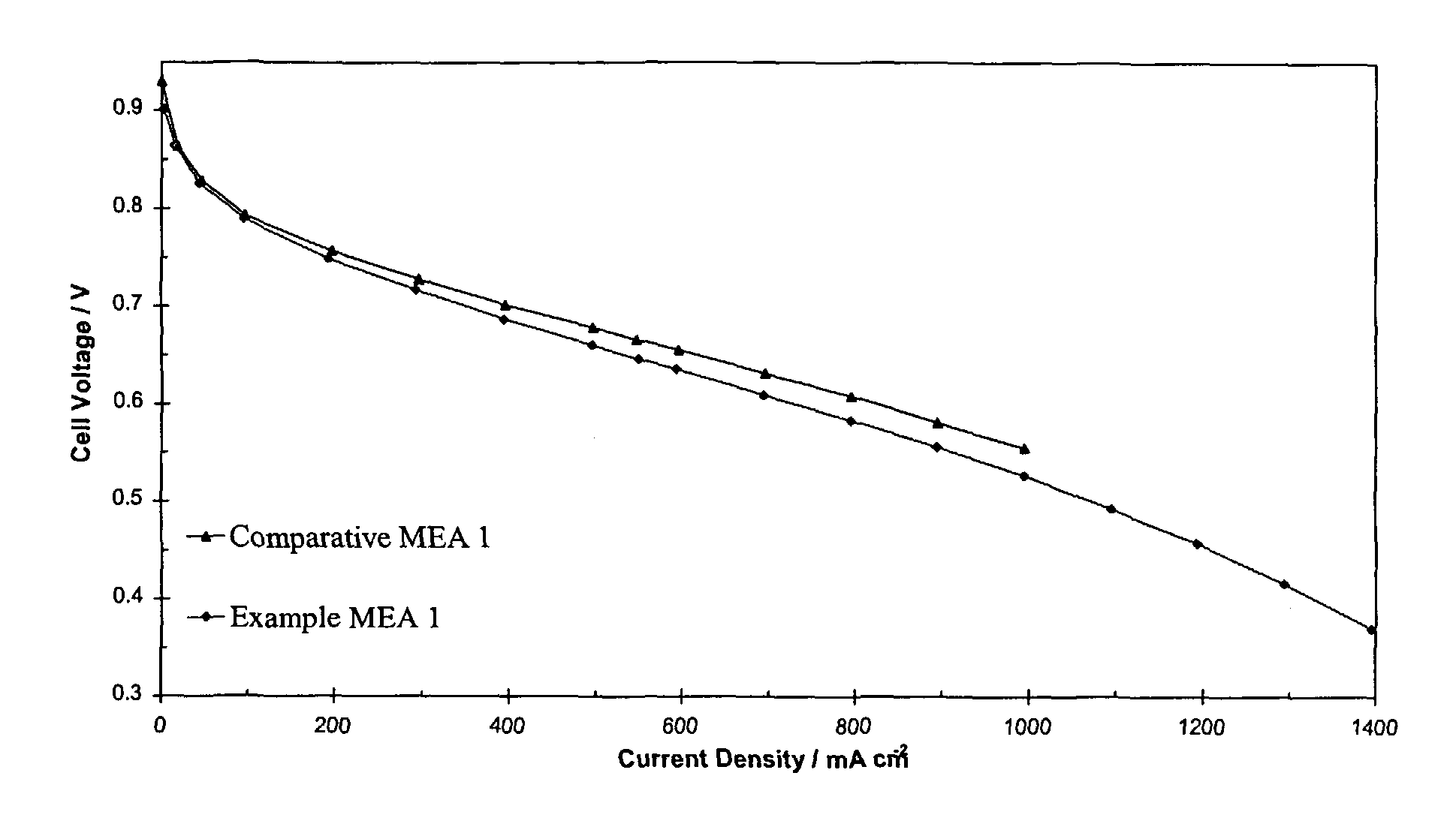
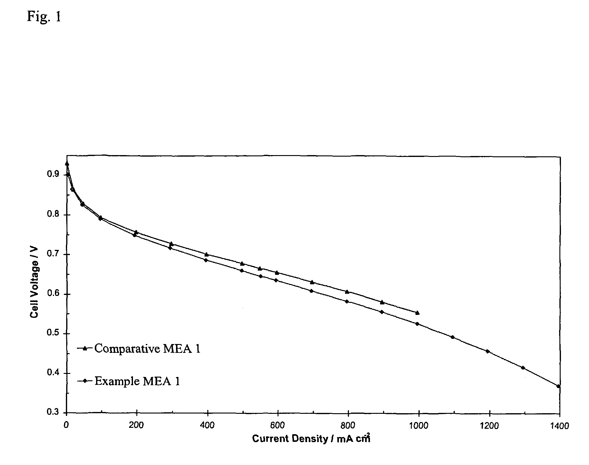
[0069]Example MEA 1 was prepared using two gas diffusion substrates produced according to Example 1. Carbon / PTFE base layers were applied to one surface of each gas diffusion substrate. The gas diffusion substrates were positioned either side of a catalysed perfluorinated sulphonic acid membrane, with the base layers facing the membrane, and the assembly was laminated together. Comparative MEA 1 was prepared in exactly the same way except that the gas diffusion substrates were Toray®TGP-H-060 paper of approximately the same thickness as the gas diffusion substrates according to Example 1.

[0070]Both MEAs were tested in a fuel cell at 65° C. with 14.9 kPa hydrogen pressure and 14.9 kPa air pressure. FIG. 1 shows that the performance of Example MEA 1 was comparable to the performance of Comparative MEA 1.


PUM

PropertyMeasurementUnit
Temperatureaaaaaaaaaa
Lengthaaaaaaaaaa
Lengthaaaaaaaaaa

Abstract

A gas diffusion substrate includes a non-woven network of carbon fibres, the carbon fibres are graphitised but the non-woven network has not been subjected to a graphitisation process. A mixture of graphitic particles and hydrophobic polymer is disposed within the network. The longest dimension of at least 90% of the graphitic particles is less than 100 μm. A process for manufacturing gas diffusion substrates includes depositing a slurry of graphitised carbon fibres onto a porous bed forming a wet fibre network, preparing a suspension of graphitic particles and hydrophobic polymer, applying onto, and pulling the suspension into, the network, and drying and firing the network. Another process includes mixing a first slurry of graphitic particles and hydrophobic polymer with a second slurry of graphitised carbon fibres and liquid forming a third slurry, depositing the third slurry onto a porous bed forming a fibre-containing layer, and drying and firing the layer.

Description

[0001]This application is the U.S. National Phase application of PCT International Application No. PCT / GB2005 / 002371, filed Jun. 15, 2005, and claims priority of British Patent Application No. 0413324.5, filed Jun. 15, 2004.FIELD OF THE INVENTION[0002]The present invention relates to gas diffusion substrates, particularly to gas diffusion substrates that are used in fuel cells such as polymer electrolyte membrane fuel cells. The invention further relates to processes for manufacturing gas diffusion substrates.BACKGROUND OF THE INVENTION[0003]A fuel cell is an electrochemical cell comprising two electrodes separated by an electrolyte. A fuel, e.g. hydrogen or methanol, is supplied to the anode and an oxidant, e.g. oxygen or air, is supplied to the cathode. Electrochemical reactions occur at the electrodes, and the chemical energy of the fuel and the oxidant is converted to electrical energy and heat. Fuel cells are a clean and efficient power source, and may replace traditional power...

Claims


Application Information

Patent Timeline
IPC IPC(8): B01D53/22H01M4/88H01M8/10H01M4/96H01M4/86H01M8/02
CPCH01M4/8605H01M4/8642H01M8/0234H01M8/0243Y02E60/50Y02P70/50H01M4/86H01M4/88H01M8/10H01M4/96
Inventor QUAYLE, GEORGE THOMASROWE, JULIA MARGARETSHARMAN, JONATHAN DAVID BRERETONSIODLAK, JULIAN ANDREWWALKER, NIGEL JULIANFLETCHER, ANDREW JAMES
Owner TECHN FIBER PRODS
Why Eureka
Try Eureka