
High breakdown voltage semiconductor circuit device

a semiconductor circuit and high breakdown voltage technology, applied in the field of semiconductor circuit devices, can solve the problems of inability to shorten the gate electrode, and achieve the effect of high breakdown voltage and high integration and breakdown voltag

Inactive Publication Date: 2012-03-13
HITACHI LTD
View PDF17 Cites 10 Cited by
  • Summary
  • Abstract
  • Description
  • Claims
  • Application Information

AI Technical Summary

Benefits of technology

The present invention provides an element structure for a MOS transistor that can achieve both high integration and high breakdown voltage. By using a semiconductor region separated by dielectric material for isolation, the transistor includes a first semiconductor region as a lightly doped drain region and a second semiconductor region with higher impurity concentration. The second semiconductor region is placed under the source electrode and helps to relax electric field concentration points. The MOS transistor also includes a field oxide layer which adjoins at least part of a surface of the first semiconductor region. The thickness of the insulating layer and the semiconductor layer is set to 4 μm or less and 30 μm or more, respectively. The semiconductor device includes at least one first and second conductivity type MOS transistor, and the transistors are formed in a semiconductor region. Overall, the invention provides an element structure that allows for high integration and high breakdown voltage of MOS transistors for supplying high power supply voltage to a high voltage side gate driving circuit for the top arm.

Problems solved by technology

Thus, such an element including a parasitic junction FET as a channel has a structural drawback in that the shortening of the gate electrode is impossible.

Method used


Image

  • High breakdown voltage semiconductor circuit device
  • High breakdown voltage semiconductor circuit device
  • High breakdown voltage semiconductor circuit device

Examples


embodiment 1

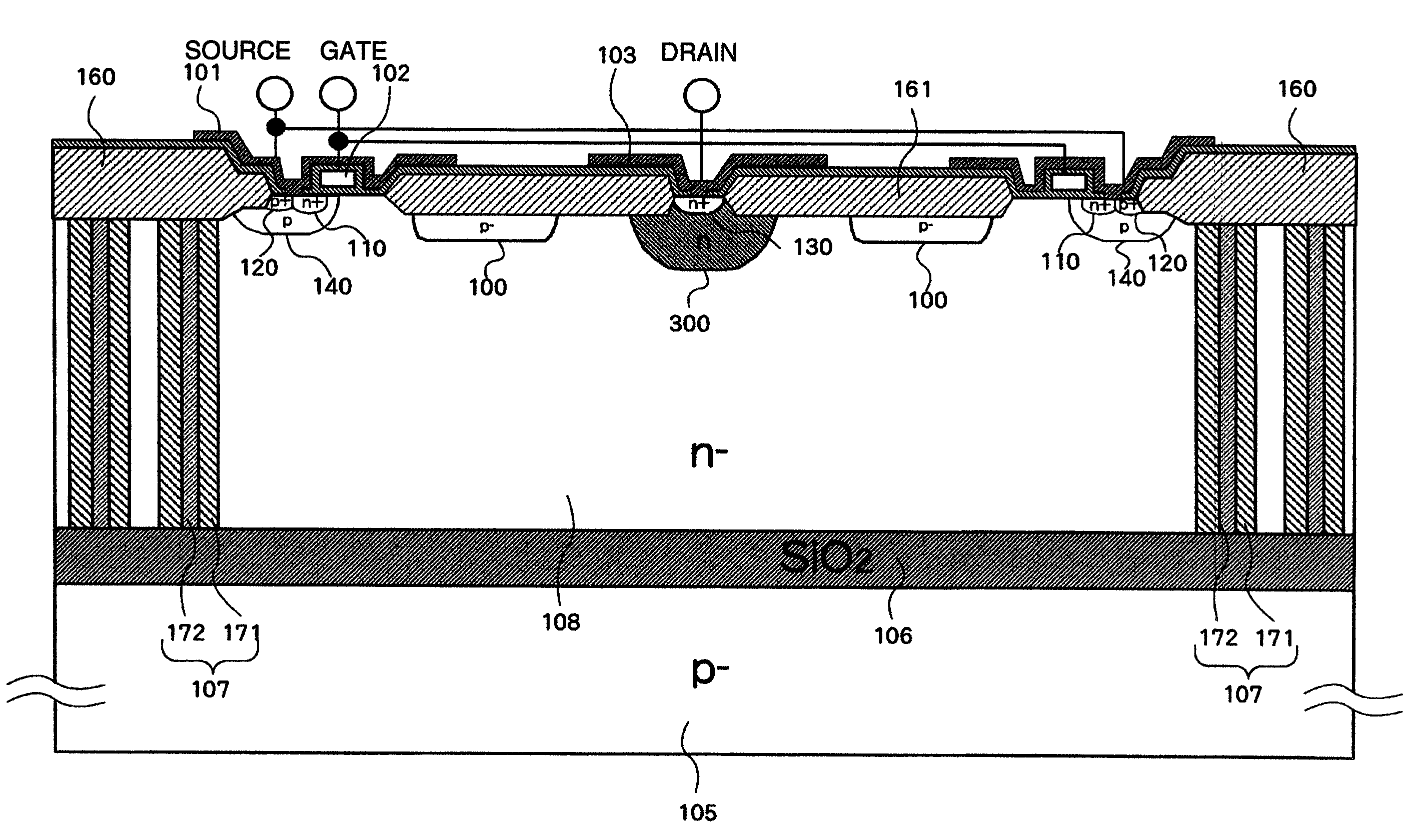
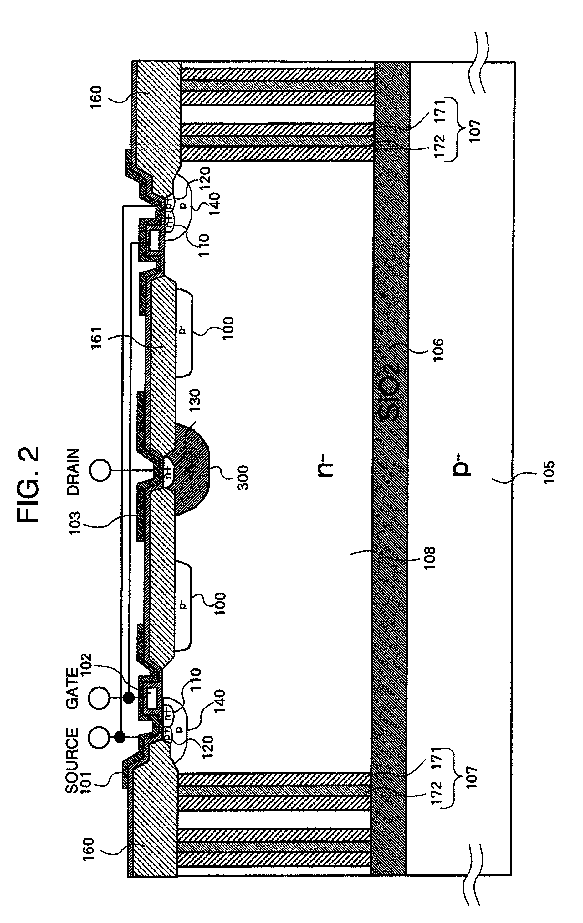
[0048]First, the details of the dielectric isolation semiconductor device 10 in accordance with a first embodiment of the present invention will be described referring to FIGS. 2 and 3.

[0049]FIG. 2 is a cross-sectional view showing the dielectric isolation semiconductor device 10 in accordance with the first embodiment. In the first embodiment, the present invention is applied to a dielectric isolation semiconductor device including a high breakdown voltage n-MOS transistor provided with an n-type channel. In FIG. 2, elements other than the n-MOS transistor are omitted for brevity. Incidentally, while a p-type semiconductor is employed for a semiconductor substrate, especially the silicon support substrate 105, in this embodiment, it is also possible to employ an n-type semiconductor for the semiconductor substrate.

[0050]The so-called “SOI substrate” is formed by stacking a high-resistance (i.e. low impurity concentration) n-type silicon active layer 108 on the silicon support subst...

embodiment 2

[0073]First, a dielectric isolation semiconductor device in accordance with a second embodiment of the present invention will be described below.

[0074]FIG. 7 is a cross-sectional view showing the principal part of the dielectric isolation semiconductor device in accordance with the second embodiment. In the dielectric isolation semiconductor device of the second embodiment, a p-type impurity diffusion region 200 is formed on the inner side face of the dielectric isolation region 107.

[0075]The p-type impurity diffusion region 200 makes contact with the p-type channel region 140 in the vicinity of the silicon surface. In this embodiment, when reverse voltage is applied between the source and the drain, the spread of the depletion layer from the source side starts from the p-type channel region 140 and the p-type impurity diffusion region 200, thereby the spread of the depletion layer in the horizontal direction is facilitated in comparison with the structure in the first embodiment. T...

embodiment 3

[0076]Next, a dielectric isolation semiconductor device in accordance with a third embodiment of the present invention will be described below.

[0077]FIG. 8 is a cross-sectional view showing the dielectric isolation semiconductor device in accordance with the third embodiment. The dielectric isolation semiconductor device of the third embodiment, employing the SOI substrate of the high breakdown voltage n-channel MOS (NMOS) transistor of the first embodiment, further includes a high breakdown voltage p-channel MOS (PMOS) transistor. While the NMOS transistor and the PMOS transistor are adjoining each other in FIG. 8, they may also be separated from each other as long as an NMOS transistor and a PMOS transistor are implemented on one SOI substrate. The PMOS transistor in this embodiment is configured in a region (area) surrounded by two dielectric isolation regions 270 which are formed simultaneously with, in the same structure as, and by the same process as the two dielectric isolati...


PUM


Abstract

In a high breakdown voltage semiconductor element among elements integrated together on an SOI substrate in which its rated voltage is shared between an embedded oxide layer and a drain region formed by an element active layer, both high integration and high breakdown voltage are realized while also securing suitability for practical implementation and practical use. The high breakdown voltage is realized without hampering size reduction of the element by forming an electrically floating layer of a conductivity type opposite to that of the drain region at the surface of the drain region. Further, the thickness of the embedded oxide layer is reduced to a level suitable for the practical implementation and practical use by setting the thickness of the element active layer of the SOI substrate at 30 μm or more.

Description

BACKGROUND OF THE INVENTION[0001]The present invention relates to a semiconductor device employing dielectric isolation for insulation between elements, and in particular, to a semiconductor device for optimally controlling a power device for driving a high power motor.[0002]A dielectric isolation semiconductor device (semiconductor device employing dielectric isolation for insulation between elements) is sometimes employed as a semiconductor device for controlling a power device. The dielectric isolation semiconductor device is a semiconductor device in which a high breakdown voltage element, a high current output circuit and a low breakdown voltage logic circuit are integrated together, for example, and each element is surrounded by dielectric material (e.g. silicon dioxide film) and thereby insulated from the substrate and other elements against high voltage. For example, a dielectric isolation semiconductor device for driving a motor includes various circuits such as a gate driv...

Claims


Application Information

Patent Timeline
Patent Type & Authority Patents(United States)
IPC IPC(8): H01L29/66H01L21/02H01L29/786H01L21/70H01L27/12
CPCH01L27/1203H01L29/0619H01L29/0634H01L29/0878H01L29/1095H01L29/402H01L29/41775H01L29/66325H01L29/66681H01L29/7394H01L29/7824H01L21/76283H01L21/76286
Inventor WATANABE, ATSUO
Owner HITACHI LTD
Learn More