
Bearing unit, motor using the bearing unit, and electronic equipment using the motor

a technology of bearing unit and bearing shaft, which is applied in the direction of liquid fuel engines, instruments, machines/engines, etc., can solve the problems of increasing the possibility of lubricating oil leakage, shortening the life of a product using the bearing unit b>100/b>, and reducing the amount of lubricating oil, so as to reduce the prevent the leakage of lubricating, and reduce the effect of rotational friction of the sha

Inactive Publication Date: 2012-03-13
SONY CORP
View PDF13 Cites 3 Cited by
  • Summary
  • Abstract
  • Description
  • Claims
  • Application Information

AI Technical Summary

Benefits of technology

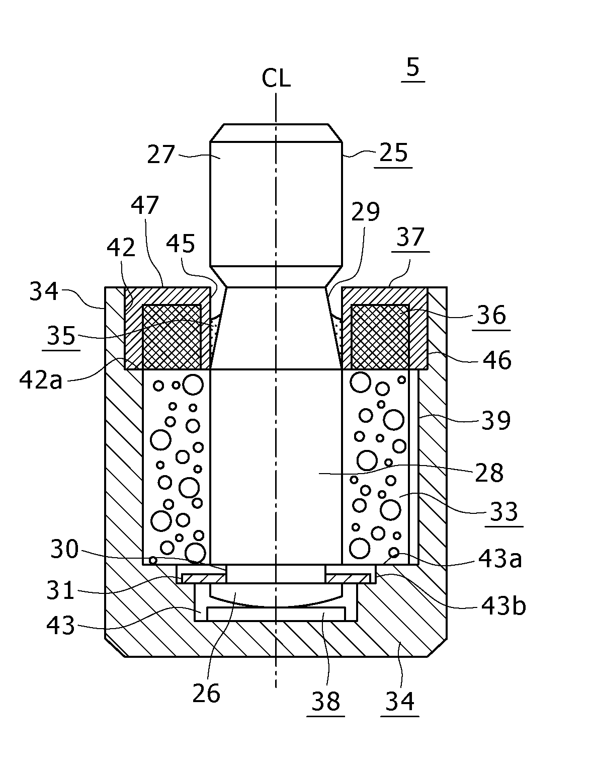
The present invention provides a bearing unit that prevents the decrease in the amount of lubricating oil due to the expansion of air in the housing and the leakage of lubricating oil from the gap between the rotating shaft and the radial bearing. This is achieved by using a sealing member to close the open end of the housing and prevent the leakage of lubricating oil. The invention also provides a motor and electronic equipment that use the bearing unit. The holding member and sealing member prevent the contact of the holding member and the shaft and prevent the evaporation of lubricating oil from the open end of the housing. This increases the life of the product and reduces the likelihood of failure.

Problems solved by technology

As a result, a decrease in amount of the lubricating oil due to the expansion of the remaining air becomes greater than a loss due to evaporation, thus shortening the life of a product using the bearing unit 100.
In this case, the lubricating oil moves under its own weight toward the open end of the housing 104, causing an increase in possibility of the leakage of the lubricating oil.
Further, when the temperature of the product rises, the viscosity of the lubricating oil decreases to cause a further increase in possibility of the leakage of the lubricating oil.

Method used


Image

  • Bearing unit, motor using the bearing unit, and electronic equipment using the motor
  • Bearing unit, motor using the bearing unit, and electronic equipment using the motor
  • Bearing unit, motor using the bearing unit, and electronic equipment using the motor

Examples


Embodiment Construction

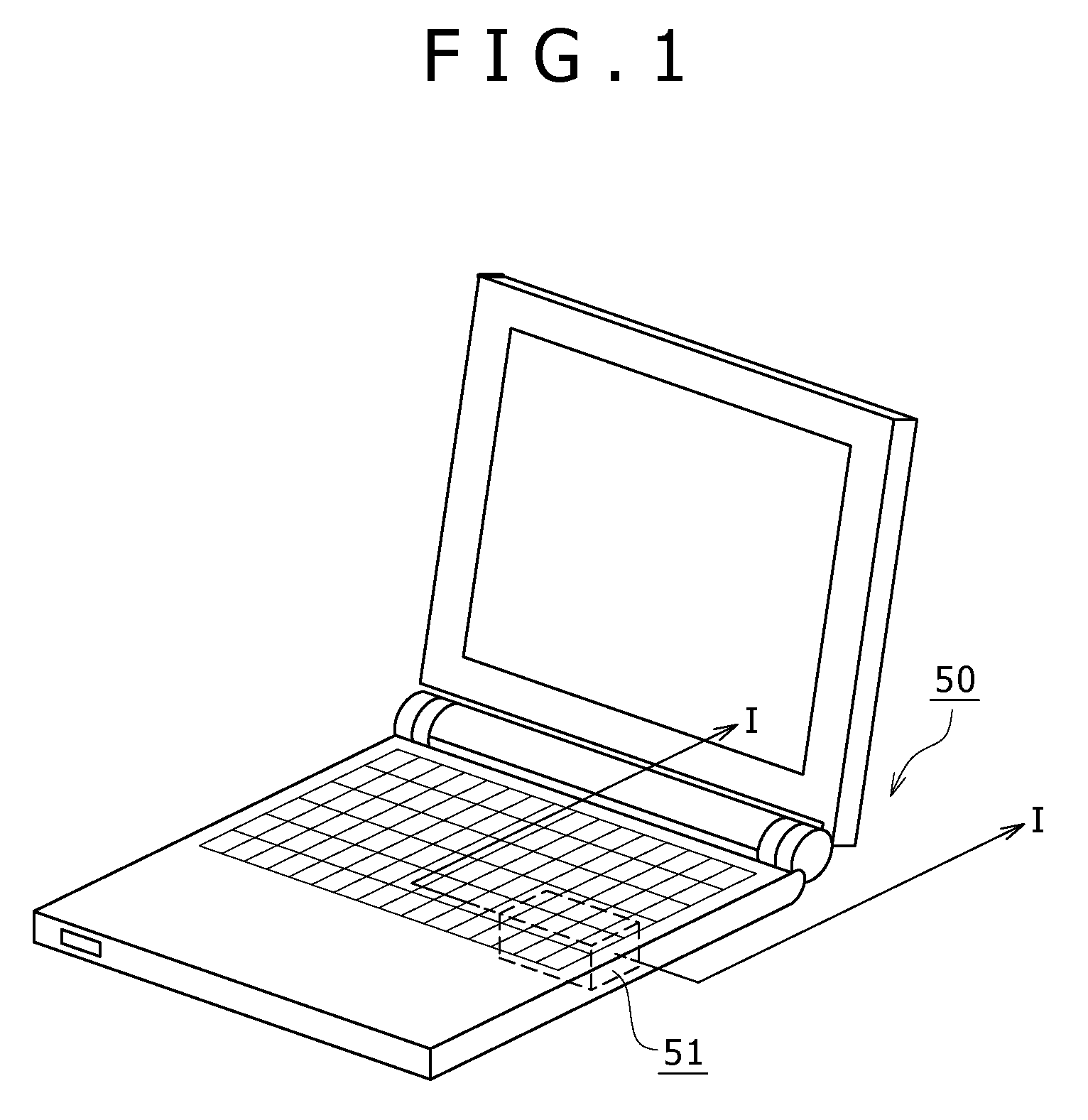
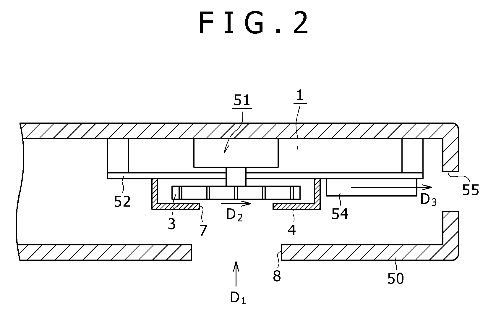
[0033]A motor using a bearing unit according to a preferred embodiment of the present invention will now be described with reference to the drawings. Referring to FIG. 1, there is shown a portable computer 50 as an information processing device for performing arithmetic computations on various kinds of information. The portable computer 50 is an example of electronic equipment. As shown in FIG. 1, the portable computer 50 includes a radiating device 51 using the motor according to the preferred embodiment. As shown in FIG. 3, the radiating device 51 has a metal base 52 mounted inside of a housing of the computer 50. Mounted on the metal base 52 are a heat generating element 53 such as a CPU (Central Processing Unit) electrically driven to generate heat, a heat sink 54, a motor 1 according to the embodiment of the present invention, a fan 3 rotationally driven by the motor 1, and a fan case 4 accommodating the fan 3. The motor 1 for rotationally driving the fan 3 in the radiating dev...


PUM


Abstract

Disclosed herein is a bearing unit including a shaft; a radial bearing for supporting the outer circumferential surface of the shaft; a housing for accommodating the radial bearing, the housing having an open end from which the shaft is inserted and a closed end opposite to the open end in the axial direction of the shaft; a lubricating oil filled in the housing to reduce rotational friction of the shaft; a holding member provided at the open end of the housing for holding the lubricating oil; and a sealing member for closing the open end of the housing to prevent the leakage of the lubricating oil; wherein the sealing member having a side wall portion interposed between the holding member and the shaft and opposed to the outer circumferential surface of the shaft.

Description

CROSS REFERENCES TO RELATED APPLICATIONS[0001]The present invention contains subject matter related to Japanese Patent Application JP 2007-231843 filed in the Japan Patent Office on Sep. 6, 2007, the entire contents of which being incorporated herein by reference.BACKGROUND OF THE INVENTION[0002]1. Field of the Invention[0003]The present invention relates to a bearing unit for rotatably supporting a rotating shaft or rotatably supporting a rotating member to a shaft, motor using the bearing unit and electronic equipment using the motor.[0004]2. Description of the Related Art[0005]As a bearing unit for rotatably supporting a rotating shaft, the configuration shown in FIG. 9 is widely used (see Japanese Patent Laid-Open No. 2005-69382). Referring to FIG. 9, such a bearing unit 100 is generally shown. The bearing unit 100 has a rotating shaft 101, a radial bearing 102 for rotatably supporting the outer circumferential surface of the rotating shaft 101, a thrust bearing 103 for rotatabl...

Claims


Application Information

Patent Timeline
Patent Type & Authority Patents(United States)
IPC IPC(8): H02K5/16H02K7/08
CPCF04D29/057G06F1/203H02K7/085F04D25/062F04D25/0626F16C2380/26F16C33/104
Inventor YAZAWA, KENICHIROSATO, HIROSHIKAKINUMA, YOSHIAKIKOYANAGI, ICHIRO
Owner SONY CORP
Learn More