Charged particle beam decelerating device and method, and X-ray generating apparatus using the same

a technology of x-ray generating apparatus and charged particle, which is applied in the direction of x-ray tubes, particle separator tube details, nuclear engineering, etc., can solve the problems of vacuum deterioration, difficult to insert a conductor or a low-loss dielectric for changing the wavelength of in-tubes, and difficulty in achieving system miniaturization and cost reduction. , to achieve the effect of miniaturization of the system

Active Publication Date: 2012-03-20
IHI CORP +1
View PDF19 Cites 3 Cited by
  • Summary
  • Abstract
  • Description
  • Claims
  • Application Information

AI Technical Summary

Problems solved by technology

However, in this system, when the electron beam collided with the laser beam collides with a beam dump or the like finally, an intense X-ray generated by the collision may cause problems.
Accordingly, the same system using a high-energy electron beam requires large-scale shielding, and it is difficult to achieve miniaturization of the system and cost reduction.
Accordingly, from the viewpoint of suppression of electric discharge, it is very difficult to insert a conductor or a low-loss dielectric for changing the in-tube wavelength as described above into the waveguide with a strong electric field.
In addition, a gas may discharges from the low-loss dielectric, and thus there are problems in that the vacuum deteriorates and electric discharge occurs.

Method used


Image

  • Charged particle beam decelerating device and method, and X-ray generating apparatus using the same
  • Charged particle beam decelerating device and method, and X-ray generating apparatus using the same
  • Charged particle beam decelerating device and method, and X-ray generating apparatus using the same

Examples


first embodiment

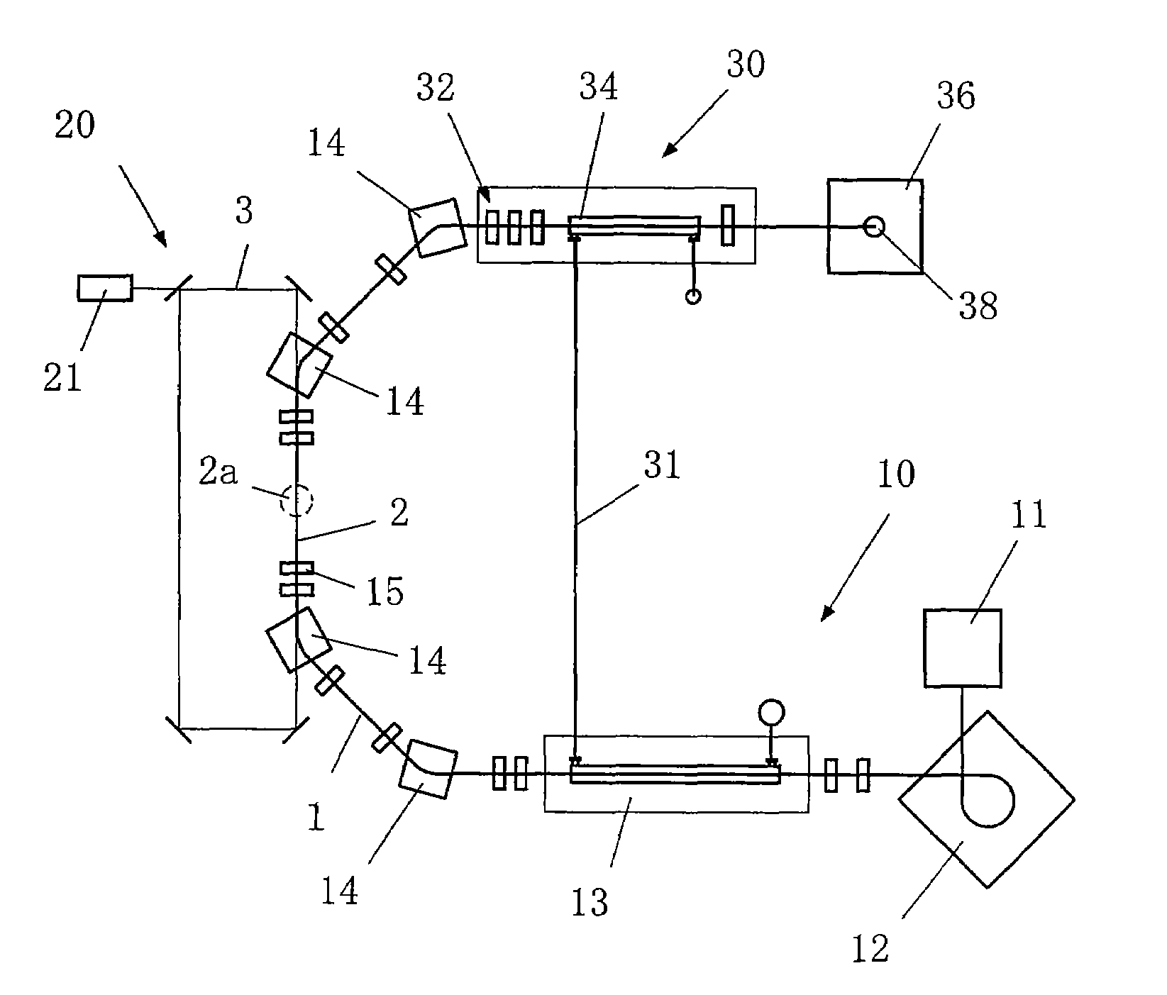
[0069]FIG. 6A is a diagram showing the charged particle beam decelerating device 30 according to the invention. In this drawing, a phase synchronizing device40 is a decelerating tube moving device 42 for moving the high-frequency cavity 34 along the orbit of the electron beam 1.

[0070]A high-frequency electric field is transmitted from a high-frequency source 34a to the upstream side of the high-frequency cavity 34 to be transmitted to the downstream side in the high-frequency cavity 34, and be discharged to a high-frequency dump 34b from the downstream side.

[0071]Expandable bellows 41a and 41b are provided at the upstream end and the downstream end of the high-frequency cavity 34, respectively, to move the high-frequency cavity 34 along the orbit of the electron beam 1 while keeping the inside of the high-frequency cavity 34 in a vacuum state.

[0072]The decelerating tube moving device 42 is, for example, a spiral screw, a rack and pinion, and a linear actuator. The decelerating tube ...

second embodiment

[0079]FIG. 7 is a diagram showing the charged particle beam decelerating device 30 according to the invention. In this drawing, the phase synchronizing device 40 is an α-magnet control device 44 for controlling a magnetic flux density B of the above-described α-magnet 12 changing the orbit of the electron beam 1 with a magnetic field.

[0080]When E denotes energy of the beam, the electron beam 1 in a constant magnetic field B draws a circular orbit due to a relational expression (1), that is, E[GeV]=0.3×B×R, where R denotes radius of curvature.

[0081]For example, electron beam energy E is 50 MeV=0.05 GeV and the magnetic flux density B is 0.4 T, the radius of curvature is 0.417 m.

[0082]When the orbit length of beam orbit A, B is changed by the α-magnet 12 by 32 mm (length corresponding to the in-tube wavelength of the high-frequency electric field 4), it is preferable that a difference in radius of curvature is about 6.8 mm. When the radius of curvature of the beam orbit A is 150 mm, i...

fourth embodiment

[0091]FIG. 9 is a diagram showing the charged particle beam decelerating device 30 according to the invention. In this drawing, the phase synchronizing device 40 is a deflecting magnet control device 48 for controlling the magnetic flux density of the deflecting magnet 14 deflecting the orbit of the electron beam 1.

[0092]When the magnetic flux density of the deflecting magnet 14 is weakened, change from the beam orbit A to the beam orbit B is caused, and the beam orbit length is changed by an amount corresponding to the change. By adjusting the beam orbit length, time when the electron beam 1 reaches the high-frequency cavity can be adjusted and beam energy can be arbitrarily adjusted.


PUM


Abstract

A charged particle beam decelerating device includes a high-frequency cavity 34 provided on an orbit of a charged particle beam 1, and a phase synchronizing device 40 for synchronizing the charged particle beam 1 in the high-frequency cavity with a phase of a high-frequency electric field 4. By moving the high-frequency cavity 34 or changing an orbit length of the charged particle beam 1, the charged particle beam in the high-frequency cavity is synchronized with a phase of the high-frequency electric field 4.

Description

[0001]This is a National Phase Application in the United States of International Patent Application No. PCT / JP2008 / 054931 filed Mar. 18, 2008, which claims priority on Japanese Patent Application No. 077621 / 2007, filed Mar. 23, 2007. The entire disclosures of the above patent applications are hereby incorporated by reference.TECHNICAL FIELD OF THE INVENTION[0002]The present invention relates to a charged particle beam decelerating device and method for decelerating energy of a charged particle beam, and an X-ray generating apparatus using the device and method.DESCRIPTION OF THE RELATED ART[0003]In the invention, a charged particle beam means an electron beam, an ion beam and a positron beam.[0004]It is known that a quasi-monochromatic X-ray resulting from Compton scattering is obtained by collision of an electron beam with a laser beam (for example, Non-Patent Document 1).[0005]In a “small-sized X-ray generating apparatus” of Non-Patent Document 1, as shown in FIG. 1, an electron b...

Claims


Application Information

Patent Timeline
Patent Type & Authority Patents(United States)
IPC IPC(8): H01J35/00H01J49/20H01J49/44H05H7/08
CPCG21K1/087H05G2/00H05H7/12H05H15/00
Inventor ISHIDA, DAISUKENOSE, HIROYUKIKANEKO, NAMIOSAKAI, YASUOYAMAMOTO, MASASHIUESAKA, MITSURUDOBASHI, KATSUHIROSAKAMOTO, FUMITO
Owner IHI CORP
Why Eureka
Try Eureka