Electrodialysis system and process

a technology of electrodialysis and electrodialysis system, applied in the field of improved electrodialysis (ed) apparatus, can solve the problems of limited ability to remove, limited utility of electrodialysis, both filled and unfilled varieties, etc., to improve the match of electrical conductivity, reduce the incidence of extreme voltage disparities, and the effect of closer matching of mineral burdens

Active Publication Date: 2012-03-27
BL TECH INC
View PDF5 Cites 11 Cited by
  • Summary
  • Abstract
  • Description
  • Claims
  • Application Information

AI Technical Summary

Benefits of technology

[0020]One or more of the foregoing problems or limitations are addressed in accordance with one aspect of the present invention, by a treatment or deionization system for alimentary or similar fluids, such as a whey or plant syrup demineralization system, wherein an arrangement of plural electrically operated membrane separation units, including electrodialysis (ED), reversing electrodialysis (EDR), filled cell electrodialysis (EDI), and / or filled cell reversing electrodialysis (EDIR) units operate to demineralize a feed stream and to transfer minerals or other components of the feed into one or more concentrate streams. The processing units, each having one or more inlets and outlets, are arranged in groupings of one or more units in an order corresponding generally to the direction of the bulk movement of the feed fluid which is to be treated, and the groups form process-related stages with two or more stages in a treatment line configured such that the concentrate stream or streams proceed from one stage to the next in a sense or order substantially opposite to that of the feed / product stream. Thus, as the feed is becoming demineralized, it passes progressively to units utilizing the earlier, less mineralized portions of the concentrate stream. With this architecture, advantageously, as the feed is treated its conductivity may drop, while as the concentrate acquires impurities from the feed its conductivity may rise, so that the mineral burden and the electrical conductivity of the feed and concentrate streams are more closely “matched” as the streams pass through each unit along the treatment line. Arranging the two fluid flows in opposite sense results in an improved match of electrical conductivity of the feed and concentrate in a processing unit, which reduces the incidence of extreme voltage disparities in the electrodialysis cells, and may also result in a closer match of the mineral burdens that reduces concentration gradients across the membranes of the processing units and thus lowers back-diffusion of certain components. Conductivity matching avoids such adverse conditions as polarization and excessive water splitting, so that control of the fluid treatment to desired set points at each stage is more readily achieved, and a common cause of scaling or fouling is eliminated.
[0021]In a treatment line having plural stages arranged in accordance with the present invention, different stages may be run with different electrical operating parameters. Alternatively, or in addition, different stages may employ different types of ED units. One system may include, e.g., unfilled ED units in one stage and EDI units in a later stage. Another embodiment of a system may be implemented entirely with (unfilled) ED treatment units, but with one stage having membranes that offer distinctly different permeability characteristics or selectivity than another stage. Operation of the system for a particular feed liquid is set by adjusting the operation of different units—for example, setting the volts per cell pair in each electrical stage—to tailor the ion removal and current efficiency in accordance with the type of unit and the fluid quality / composition prevailing in that stage, or the load or conductivity along the process line. This is done to enhance overall operation, e.g., increase process efficiency or throughput, while avoiding problems that often arise during treatment. For example, one may operate substantially everywhere below polarization, and may control to a high current level in one or more early stages along the feed conduit, yet suffer little power loss through the flow manifolds. Moreover, the different stages may operate with different but changing control regimens. For example, a first ED stage may be controlled to present a certain quality of partially-treated feed at the transition between the ED stage and an EDI stage, such that each stage avoids protein fouling, denaturing or charring, or complications that would otherwise arise in a biological fluid electrodeionization system. The process line may also be controlled to optimize throughput in other ways, for example to maximize the amount of fluid treated consistent with achieving a target level of product quality, or to enhance the removal or recovery of a specific component by altering treatment parameters in one stage that primarily affects the quality, separation or recovery of that specific component.

Problems solved by technology

The membranes used in this early ED apparatus were poorly ion selective.
The utility of electrodialysis, both filled and unfilled varieties, continues to be limited to some extent, however, by technical factors, particularly its relatively low limiting current densities and its limited ability to remove poorly ionized substances.
The latter approach is especially useful for plant (e.g., botannical) syrups whose viscosity, hence laminar layer behavior, may be highly temperature dependent, but it is further limited by the limited ability of ion exchange resins to withstand higher temperatures without impairment of their exchange functionality.
Thus, operation at high limiting current densities results in increased membrane scaling.
Such good behavior continues for only several hours, however, after which period water splitting begins and increases with time.
It has been concluded that splitting of water at conventional AX membranes at or near their limiting current densities is an unfortunate phenomenon that, for practical purposes, is unavoidable.
However, ion exchange beds and EDI systems are not equivalent in their operational requirements, and each has its own characteristics.
Furthermore, while it is technically possible to back-wash the IX granules in an EDI apparatus, back washing is generally technically difficult or quite inefficient owing to the confining dimensions of the flow cells in which the exchange beads are packed and to the many small port structures and bead traps generally present in these devices.
All of these factors make it problematic to remove any colloidal matter that may accumulate or become trapped in the filled cells.
However, for applications in the food industry, such problems may be more complex.
Protein and other components of alimentary process fluids may be sensitive to the electrochemical conditions prevailing within an EDI stack, and are potentially fouling (for anion resins in particular).
Also, the viscosity and temperature requirements of a food process will affect the practically achievable flow and treatment conditions in an EDI or EDI unit.
However, alimentary process applications present special problems.
However, the added acid is itself rapidly removed by electrodialysis, introducing a certain inefficiency of operation and requiring elevated doses of acid.
An undesirably high quantity of acid is therefore required to complete this process.
However, considerable quantities of acid and base are then required to regenerate the exchange beads, introducing both direct and environmental costs.
However, because a relatively large range of concentrations and fairly complex interactions are involved, it remains a lengthy research undertaking to identify a set of processes and operating points that will improve the performance or economics of a given alimentary fluid process.

Method used


Image

  • Electrodialysis system and process
  • Electrodialysis system and process
  • Electrodialysis system and process

Examples


Embodiment Construction

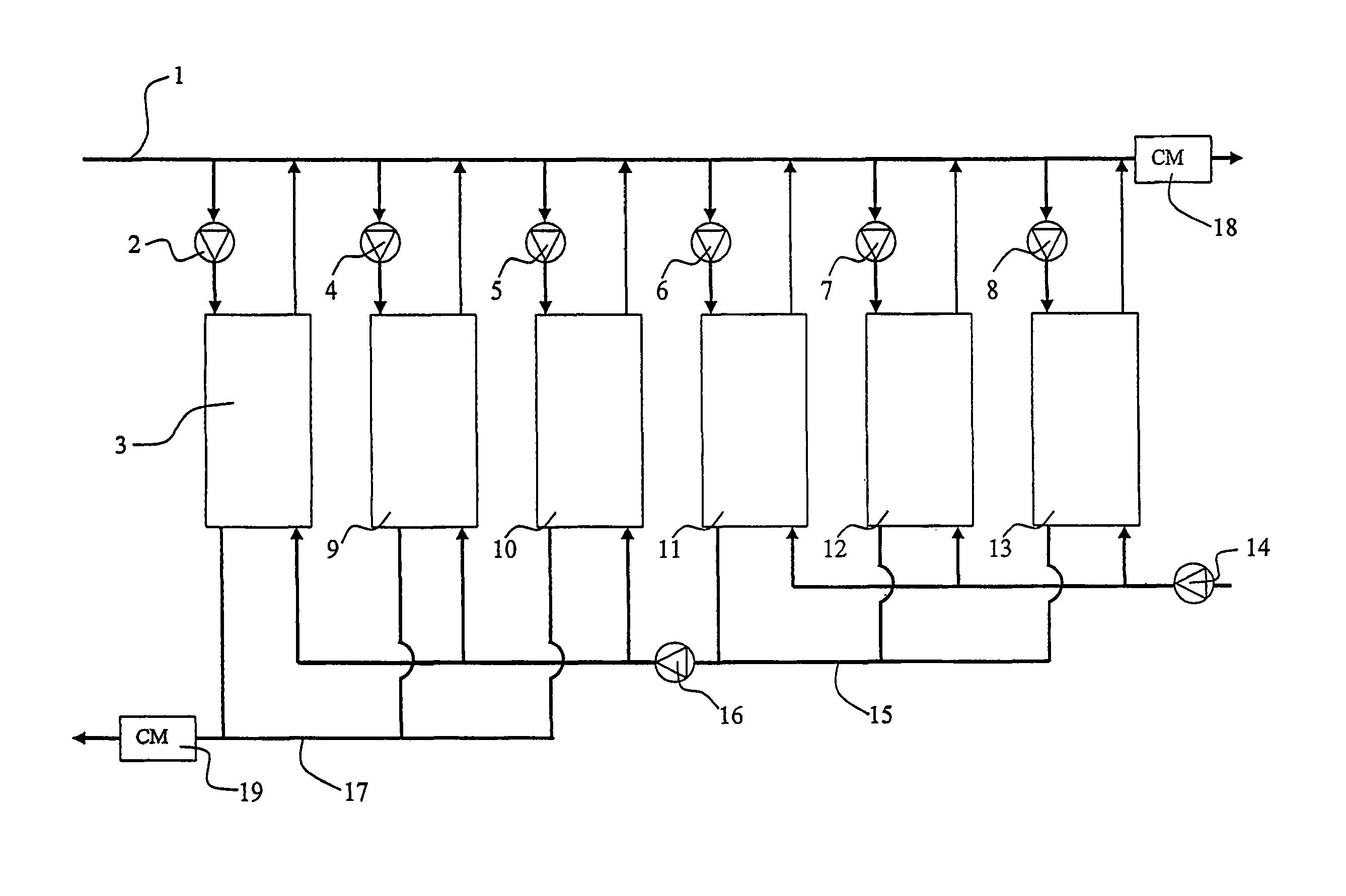
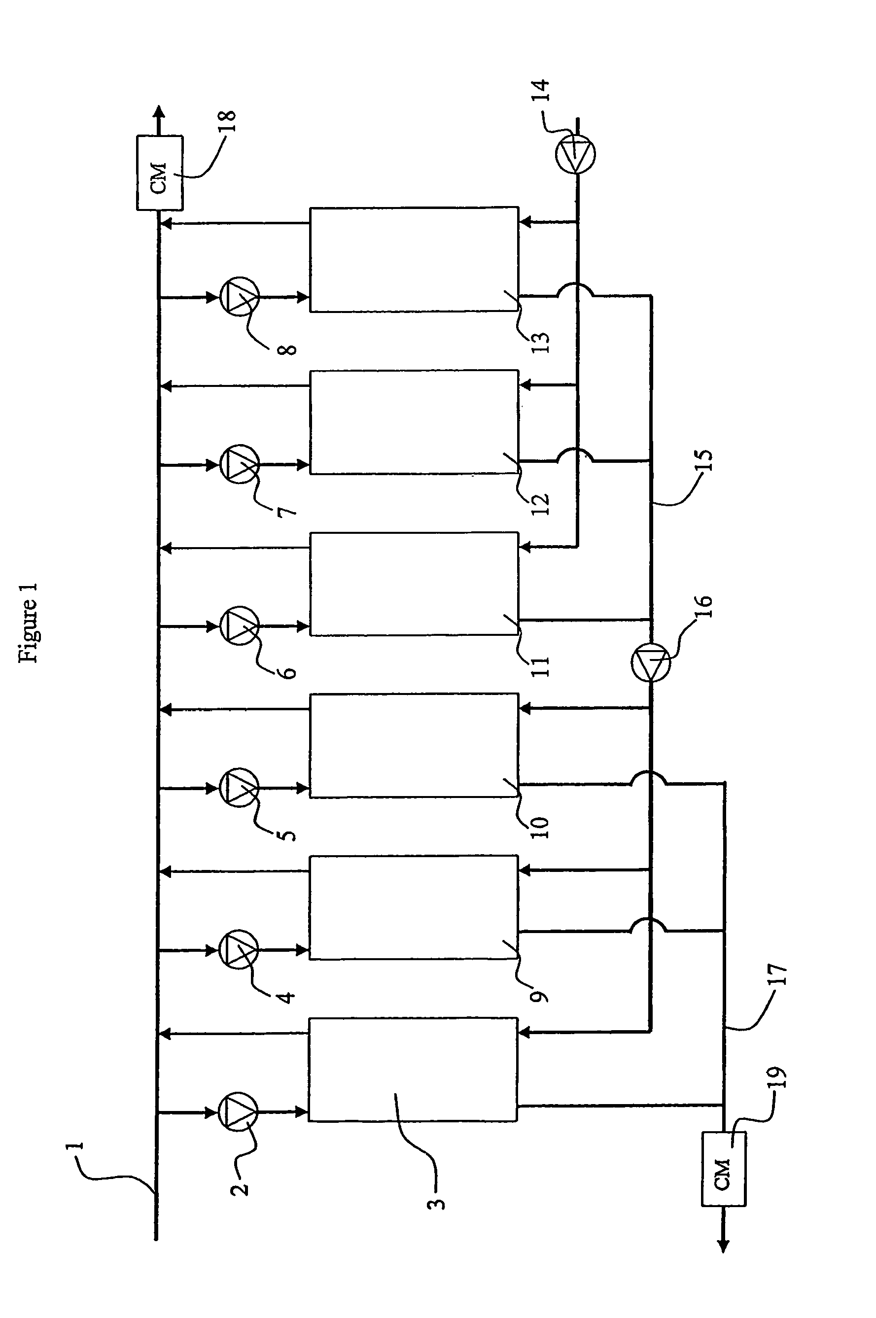
[0042]FIG. 1 shows one embodiment of a system in accordance with the invention.

[0043]The system includes a number of demineralizing units 3, 9, 10, 11, 12 and 13, such as electrodialsis or electrodeionization units, that each receive a feed from a stream of fluid to be treated, e.g., demineralized, in a process feed line 1. The units return an at least partially demineralized flow to the process feed line, as illustrated by the flow connections at the upper end of each unit in FIG. 1. Each unit requires a flow of concentrate, which it receives via conduits and ports as shown in FIG. 1 at the lower end of each unit, to carry off the salts, small molecules or other material removed from the feed fluid The terms “upper” and “lower” here simply refer to the drawings, and imply no limitation on the geometry or orientations of the units themselves, their ports or plumbing connections, which may vary. Within each unit, dilute and concentrate flow cells are arranged to capture ions from the...


PUM

PropertyMeasurementUnit
current densitiesaaaaaaaaaa
current densityaaaaaaaaaa

Abstract

A treatment system and method for continuous deionization of a biologically derived feed stream includes a plurality of electrodialysis units (3, 9, 10, 11, 12, 13) arranged in stages along a treatment line, and stages are controlled such that the feed stream attains a certain quality before entering the next stage. The feed and concentrate streams move in generally opposite sense along the line, matching fluid characteristics of dilute and concentrate cells. The treatment line has two or more stages. Systems may have phased staging operations, and cell constructions may adapt the electrodialysis units for enhanced processing of difficult process fluids. A controller sets operating potentials in different electrical stages, and simple control parameters optimize ion removal and current efficiency without polarization of the fluid. The invention also includes phased staging of reversal operation, and cell constructions or fillings that adapt the treatment cells for enhanced processing.

Description

BACKGROUND AND FIELD OF THE INVENTION[0001]This invention pertains to improved electrodialysis (ED) apparatus, and pertains more particularly to systems and processes that utilize such apparatus to treat large volumes of liquid. Generally as used herein and in the claims appended hereto, unless the context implies otherwise, the terms electrodialysis or ED shall be understood to be generic, and shall refer to devices for demineralizing, or for removal of components from, a fluid, wherein device units have alternating dilute and concentrate cells defined between sets of ion exchange membranes. These devices treat fluid passing through the dilute cells by transferring components thereof into another fluid present in the concentrate cells. Thus, the term will include various forms of electrodialysis having unfilled inter-membranes spaces or cells—i.e., shall include classical electrodialysis (ED), electrodialysis reversal (EDR); and shall also include filled-cell electrodialysis (now c...

Claims


Application Information

Patent Timeline
Patent Type & Authority Patents(United States)
IPC IPC(8): B01D61/46B01D61/42B01D61/44B01D61/48B01D61/54B01D61/58C02F1/469
CPCB01D61/422B01D61/44B01D61/46B01D61/48B01D61/54B01D61/58B01D65/02B01D65/027C02F1/469B01D2311/243B01D2317/04B01D2321/16B01D2321/162C02F1/4693C02F1/4695
Inventor BATCHELDER, BRUCEZHANG, LICARSON, WILLIAM W.
Owner BL TECH INC
Why Eureka
Try Eureka