
Electrochemical energy storage device

a technology of electrochemical energy storage and energy storage device, which is applied in the direction of electrochemical generators, non-aqueous electrolyte cells, cell components, etc., can solve the problems of reducing the number of sites containing lithium ions between layers, affecting the permeability etc., to achieve suppress the reductive decomposition of the electrolyte solution, suppress the per

Inactive Publication Date: 2012-04-03
PANASONIC CORP
View PDF11 Cites 6 Cited by
  • Summary
  • Abstract
  • Description
  • Claims
  • Application Information

AI Technical Summary

Benefits of technology

"The present invention provides a non-aqueous electrolyte solution for an electric double layer capacitor that can suppress the reductive decomposition of the electrolyte solution on the surface of activated carbon, even at increased charging voltage. The non-aqueous electrolyte solution also has good permeability of lithium ions and can form a film that can prevent the breakage of a layer structure of graphite caused by ammonium ions. This results in an electrochemical energy storage device with high energy density."

Problems solved by technology

Therefore, a non-aqueous electrolyte solution containing both a lithium and an ammonium salts at a high concentration is not obtained even now.
In the case where the non-aqueous electrolyte solution contains a high concentration of ammonium ions, however, the layer structure of graphite is broken, and thus the number of sites which contain lithium ions between layers decreases and also the decomposition of the ammonium ions arises.
As described above, however, even if a non-aqueous electrolyte solution containing a large amount of the ammonium salt is effective for activated carbon, it is unfavorable for graphite.
However, any non-aqueous electrolyte solution described above has the composition of an electrolyte solution used in a conventional non-aqueous electrolyte battery in which a lithium salt is dissolved in a low concentration, and also there is no disclosure about the use in combination with an ammonium salt.
For these reasons, in the non-aqueous electrolyte battery, a practical non-aqueous electrolyte solution containing a lithium salt and an ammonium salt dissolved in high concentrations has never been proposed.
Therefore, it has never been studied whether or not a film of fluorinated benzene has the permeability of ammonium ions in the electric double layer capacitor.

Method used


Image

  • Electrochemical energy storage device
  • Electrochemical energy storage device
  • Electrochemical energy storage device

Examples


example 2

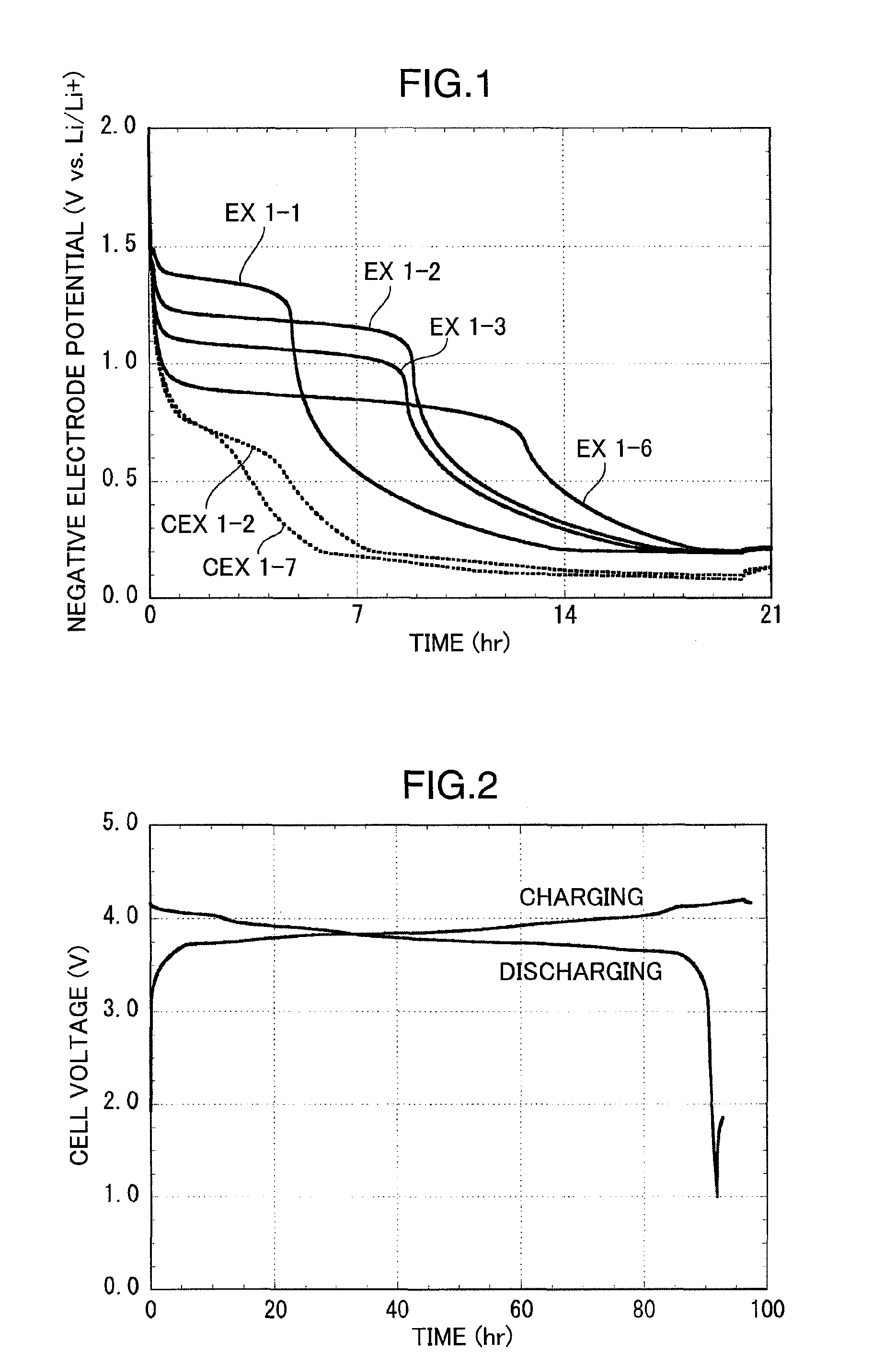
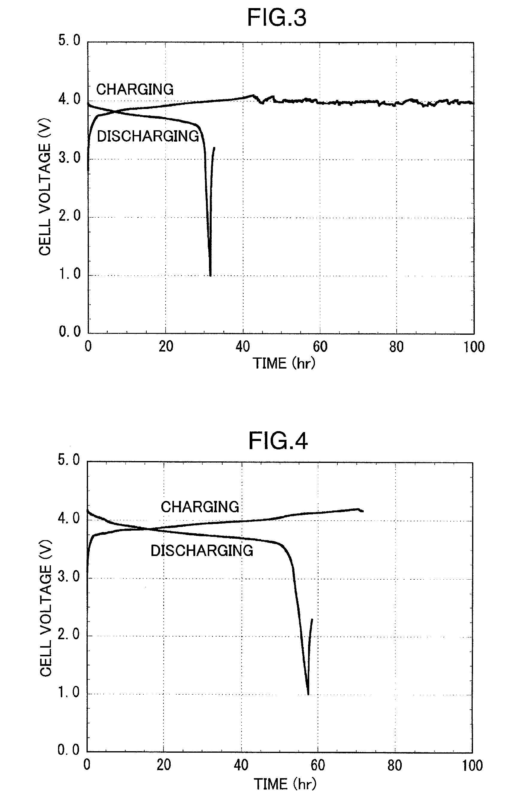
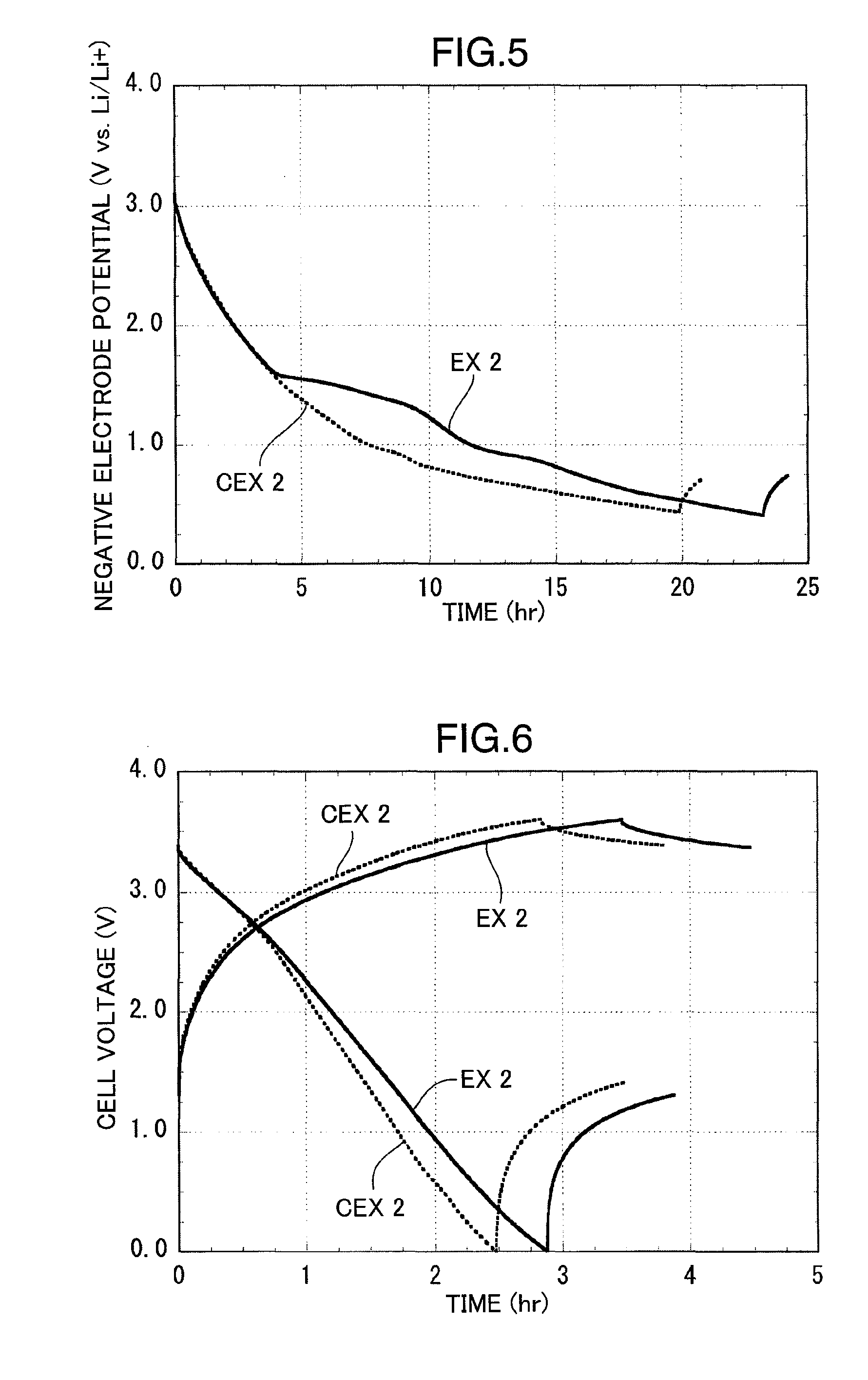
[0062]Using a positive electrode material used in a non-aqueous electrolyte battery as a positive electrode and using a polarizable material used in an electric double layer capacitor as a negative electrode, a hybrid capacitor was assembled in the following manner and then evaluated.

[0063]First, in the same manner as in Example 1, a positive electrode plate having a size of 35 mm×35 mm, in which LiCoO2 is used as the positive electrode material, was produced.

[0064]Next, an activated carbon electrode for electric double layer capacitor manufactured by Hohsen Kabushikikaisha was processed to form a negative electrode plate having a size of 35 mm×35 mm.

[0065]As the reference electrode, the same lithium metal foil as in Example 1 was used.

[0066]Besides, EC, LiBF4, TMPA.BF4 and HFB were mixed in a molar ratio (EC / LiBF4 / TMPA.BF4 / HFB=2 / 1 / 1 / 0.1) to prepare a non-aqueous electrolyte solution.

[0067]After the positive and negative electrodes produced above were disposed opposite to each other...


PUM

PropertyMeasurementUnit
negative electrode potentialaaaaaaaaaa
thicknessaaaaaaaaaa
thicknessaaaaaaaaaa

Abstract

An electrochemical energy storage device includes a negative electrode which contains a carbon material and has a negative electrode potential of 1.4 V or less relative to a lithium reference when being charged, and a non-aqueous electrolyte solution prepared by dissolving a lithium salt, an ammonium salt, and at least one kind of fluorinated benzene selected among hexafluorobenzene, pentafluorobenzene, 1,2,3,4-tetrafluorobenzene, 1,2,3,5-tetrafluorobenzene, 1,2,4,5-tetrafluorobenzene and 1,2,3-trifluorobenzene, in a non-aqueous solvent.

Description

RELATED APPLICATIONS[0001]This application is the U.S. National Phase under 35 U.S.C. §371 of International Application No. PCT / JP2007 / 053911, filed on Mar. 1, 2007, which in turn claims the benefit of Japanese Application No. 2006-125179, filed on Apr. 28, 2006, the disclosures of which Applications are incorporated by reference herein.TECHNICAL FIELD[0002]The present invention relates to an electrochemical energy storage device, and particularly to an improvement in a non-aqueous electrolyte solution for the device.BACKGROUND ART[0003]In an electric double layer capacitor in which a polarizable electrode is used as a positive electrode and a negative electrode, electrochemical energy is stored by adsorbing cations and anions in a non-aqueous electrolyte solution on an electrode surface during a charging process. The energy density of the electric double layer capacitor is increased by two different methods. One method is to decrease the amount of the electrolyte solution by increa...

Claims


Application Information

Patent Timeline
Patent Type & Authority Patents(United States)
IPC IPC(8): H01M4/58H01M4/02H01G9/00H01G11/06H01G11/22H01G11/24H01G11/30H01G11/32H01G11/38H01G11/42H01G11/46H01G11/54H01G11/60H01G11/62H01G11/86H01M4/36H01M4/587H01M10/05H01M10/0525H01M10/0567H01M10/0568H01M10/0569
CPCH01G9/038H01G9/155H01G11/62H01M4/587H01M10/0525H01M10/0567H01M10/0568H01M10/0569Y02E60/122Y02E60/13Y02E60/10H01G11/06H01M4/133H01M10/05
Inventor MATSUI, TOORUDEGUCHI, MASAKIYOSHIZAWA, HIROSHI
Owner PANASONIC CORP
Learn More