Laser separation of thin laminated glass substrates for flexible display applications

a technology of laminated glass and laser separation, which is applied in the direction of glass making apparatus, manufacturing tools, welding/soldering/cutting articles, etc., can solve the problems of glass materials, sensitivity to flaws, and electrical conductivity problems,

Active Publication Date: 2012-05-01
CORNING INC
View PDF10 Cites 62 Cited by
  • Summary
  • Abstract
  • Description
  • Claims
  • Application Information

AI Technical Summary

Problems solved by technology

While the metal substrate materials offer higher thermal capability, they are opaque and may present electrical conductivity issues.
However, a significant drawback to the glass materials is a tendency to be more brittle and the sensitivity to flaws.
The thermoplastic substrates are less sensitive to flaw size, but are limited in their thermal capability as well as their barrier properties.
Specifically, limiting water vapor and oxygen permeability of plastic substrate films is difficult, and results in an overall reduction in relative quality and life time of the associated OLEDs or organic electronic devices made on such substrate materials unless a separate barrier layer is used.
While such glass-plastic composite films are highly advantageous, applications and performance of such substrates have been severely limited due to low edge strengths caused during the cutting thereof.
However, these mechanical cutting techniques, applicable to the thicker sheet glass of approximately 0.5 mm thicknesses or greater, result in a lower yield strength when used to cut glass sheets having a thickness of less than 300 μm.
Moreover, complications arise with laminated glass substrates due to the presence of the protective polymeric layer(s).
This method still relies on a mechanical means of cutting the composite substrate by using physical contact between the substrate and cutting tool, and leads to a rupture of the laminated glass substrate along the scoring line.

Method used


Image

  • Laser separation of thin laminated glass substrates for flexible display applications
  • Laser separation of thin laminated glass substrates for flexible display applications
  • Laser separation of thin laminated glass substrates for flexible display applications

Examples


example 1

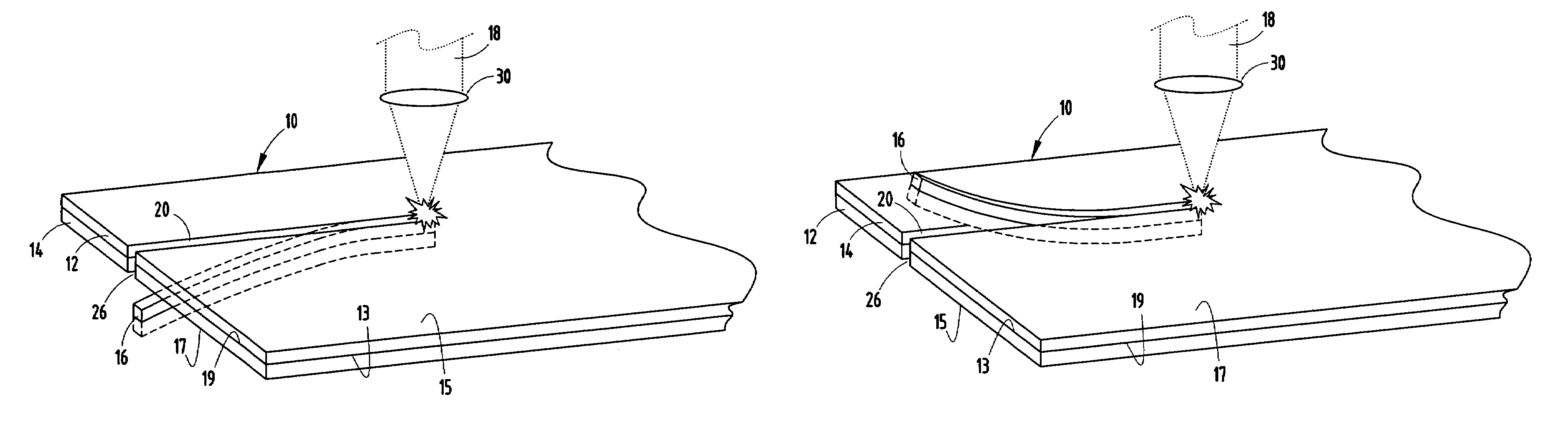
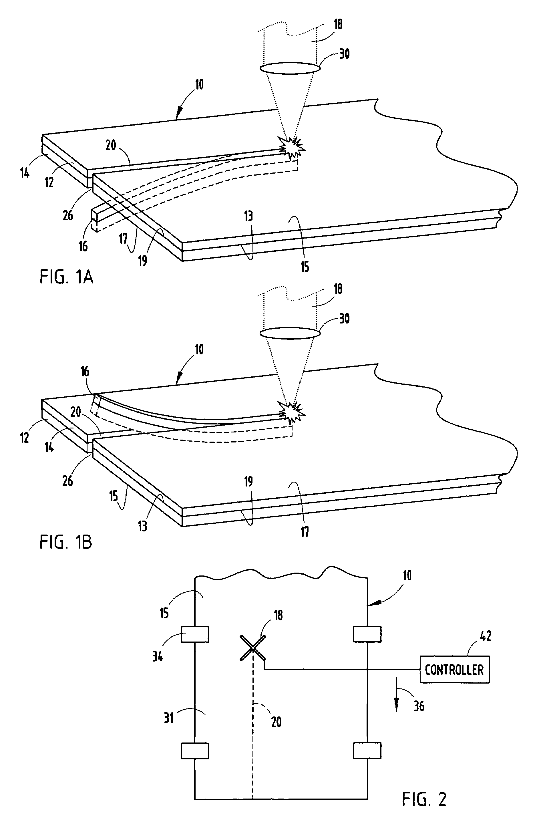
[0030]The test and sample comprised an application of a laser to the exposed glass surface of a glass sheet, and controlled cutting was obtained in a single pass of the laser. In one particular embodiment, a Synrad RF CO2 laser, available from Synrad, Inc., Mukilteo, Wash., was used as the light source. The laser was modulated at a 5 kHz rate, with the output pulses having a saw-tooth profile, with roughly 90% modulation depth. Light from the laser was vertically polarized. After a quarter-wave reflective phase retarder, polarization was transformed into a circularly polarized state prior to the focusing element 30. A 37.5 mm or 1.5 inch focal length lens was used to focus the laser light on the glass sheet surface 15. Incident laser power on the coated material surface was 23 W. Based on an M2 value of 1.2, and a beam size at the lens entrance pupil of 6 mm, the focal spot size was estimated to be 100 μm with corresponding power density of 300 kW / cm2. The sheet of coated material c...

example 2

[0031]In another example, a Synrad RF CO2 laser, as described in Example 1, was used to remove the polymeric coating in the composite material. The laser was modulated at a 5 kHz rate, with the output pulses having a saw-tooth profile and roughly 90% modulation depth. Light from the laser was vertically polarized. A 37.5 mm or 1.5 inch focal length lens was used to focus the laser light on the glass sheet. Polarization of the laser light on the coated material 10 was along the motion path. An incident power of 8 W was used. Based on a M2 value of 1.2, and a beam size at the lens entrance pupil of 6 mm, the focal spot size was estimated to be 100 μm. The sheet of coated material comprised a glass sheet having a thickness in the range of 50 microns and 100 microns and a polymer coating thereon adhered to one side of the glass. A 0211 Microsheet, as available from Corning, Inc. of Corning, N.Y., was used as the glass layer. Ultron Systems (of Haverhill, Mass.) P / N 1020R-11.8 or P / N 104...


PUM

PropertyMeasurementUnit
thicknessaaaaaaaaaa
speedaaaaaaaaaa
bend radiusaaaaaaaaaa

Abstract

A method of separating a sheet of coated brittle material comprises the steps of providing a sheet of layered brittle material comprising a brittle layer and a coating material adhered to a surface of the brittle layer and applying a laser along a separation line in the sheet, thereby cutting the coating material and separating the brittle layer by inducing a stress fracture therein.

Description

BACKGROUND OF THE INVENTION[0001]1. Field of the Invention[0002]The present application relates to the separation of a sheet of brittle material via a laser, and more particularly to laser inducement of a stress fracture within a brittle layer that has a protective coating on its surface, thereby cutting the sheet of brittle material into multiple pieces.[0003]2. Description of Related Art[0004]Flat glass substrates are a suitable substrate material for many applications where transparency, high chemical and thermal resistance, and defined chemical and physical properties are important. These applications typically include those areas where thin film and thick film technologies are utilized including displays, thin and thick film sensors, solar cells, micro-mechanical components, lithographic masks, and electronic applications, such as within sensors and membrane elements. Recent developments in many electronic applications have created a demand for new product functionalities, and ...

Claims


Application Information

Patent Timeline
Patent Type & Authority Patents(United States)
IPC IPC(8): H01L21/00
CPCB23K26/4075B23K26/38B23K26/40B32B17/1099B23K2103/50B23K26/142C03B33/09H01S3/00
Inventor GARNER, SEAN MATTHEWLI, XINGHUAWAGNER, ROBERT STEPHEN
Owner CORNING INC
Why Eureka
Try Eureka