Liquid crystal display panel

a liquid crystal display and panel technology, applied in the field of liquid crystal display panels, can solve the problems of slow response time, negative influence on the other parameters of the lc cell, and inability to achieve all these requirements at the same time, and achieve excellent contrast ratio, display characteristics, and viewing angle characteristics.

Active Publication Date: 2012-05-15
MERCK PATENT GMBH
View PDF6 Cites 24 Cited by
  • Summary
  • Abstract
  • Description
  • Claims
  • Application Information

AI Technical Summary

Benefits of technology

[0072]Specifically, preferred embodiments of the LCD panel of the present invention include: (1) the LCD panel includes substantially only the first and second electrodes as an electrode for applying a voltage to the LC medium; and (2) the second substrate includes a third electrode covering the entire display region. The embodim...

Problems solved by technology

However, the LC media known in prior art have the disadvantage that they often do not allow all these requirements to be achieved simultaneously, without negatively affecting the other parameters of the LC cell.
Among these, TN-LCD panels ha...

Method used


Image

  • Liquid crystal display panel
  • Liquid crystal display panel
  • Liquid crystal display panel

Examples


embodiment 1

[0079]The LCD panel of Embodiment 1 is a TBA-LCD panel where a pair of electrodes provided in the same substrate forms an arch-like lateral electric field in an LC medium and the alignment of LC molecules whose initial alignment is vertical alignment is controlled, thereby controlling image display.

[0080]According to the LCD panel of Embodiment 1, a plurality of pixels each constituted by a plurality of sub-pixels are arranged in a matrix pattern. The LCD panel of Embodiment 1 includes a pair of substrates composed of a TFT substrate and a counter substrate, and an LC medium interposed therebetween. More specifically, the LCD panel of Embodiment 1 includes these members in order of the TFT substrate, the LCD medium, and the counter substrate from the back face side to the observation face side. The LC medium contains nematic LCs with positive dielectric anisotropy (Δ∈>0).

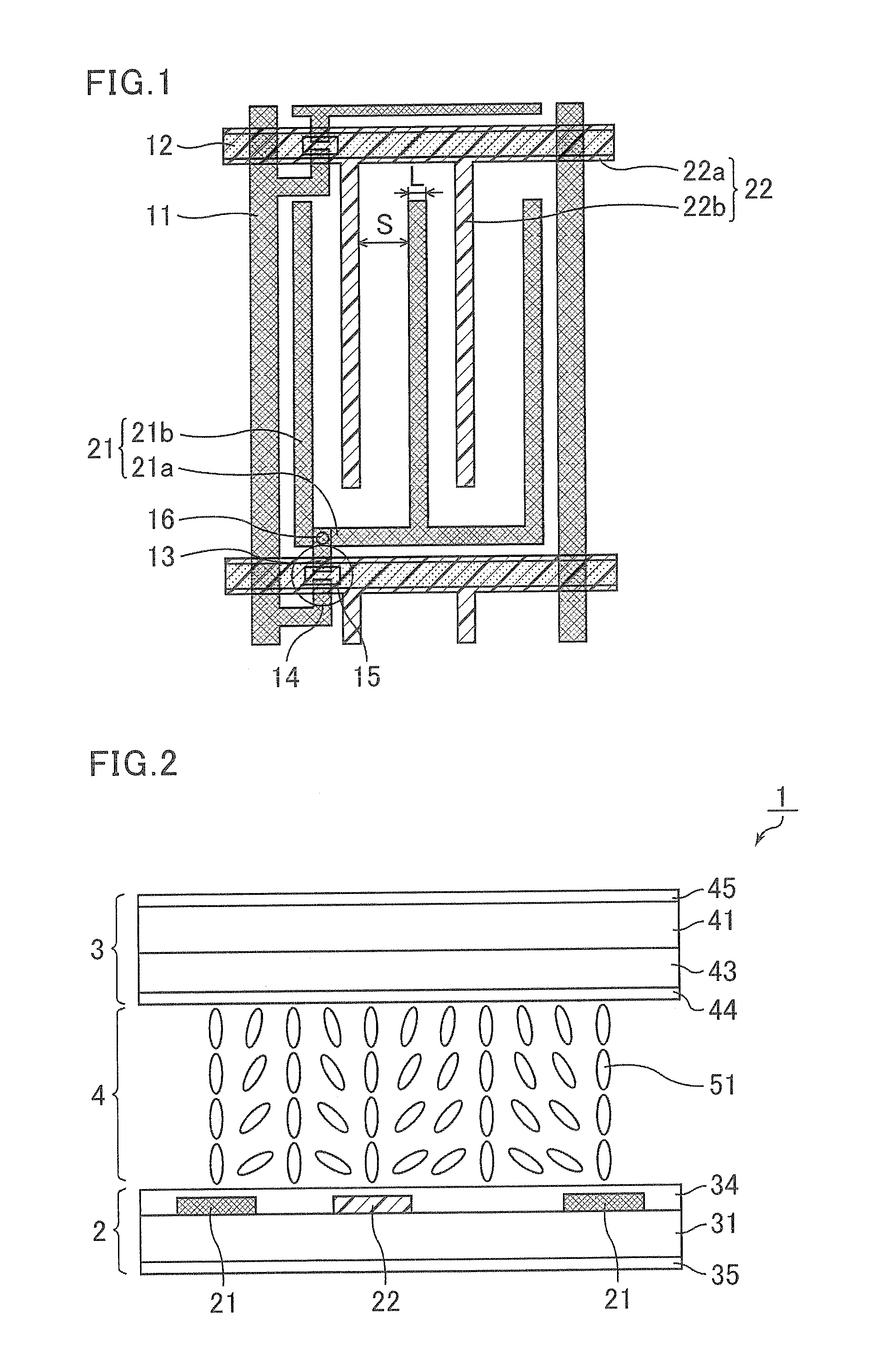
[0081]FIG. 1 is a plan view schematically illustrating a configuration per sub-pixel in a TFT substrate of the LC...

embodiment 2

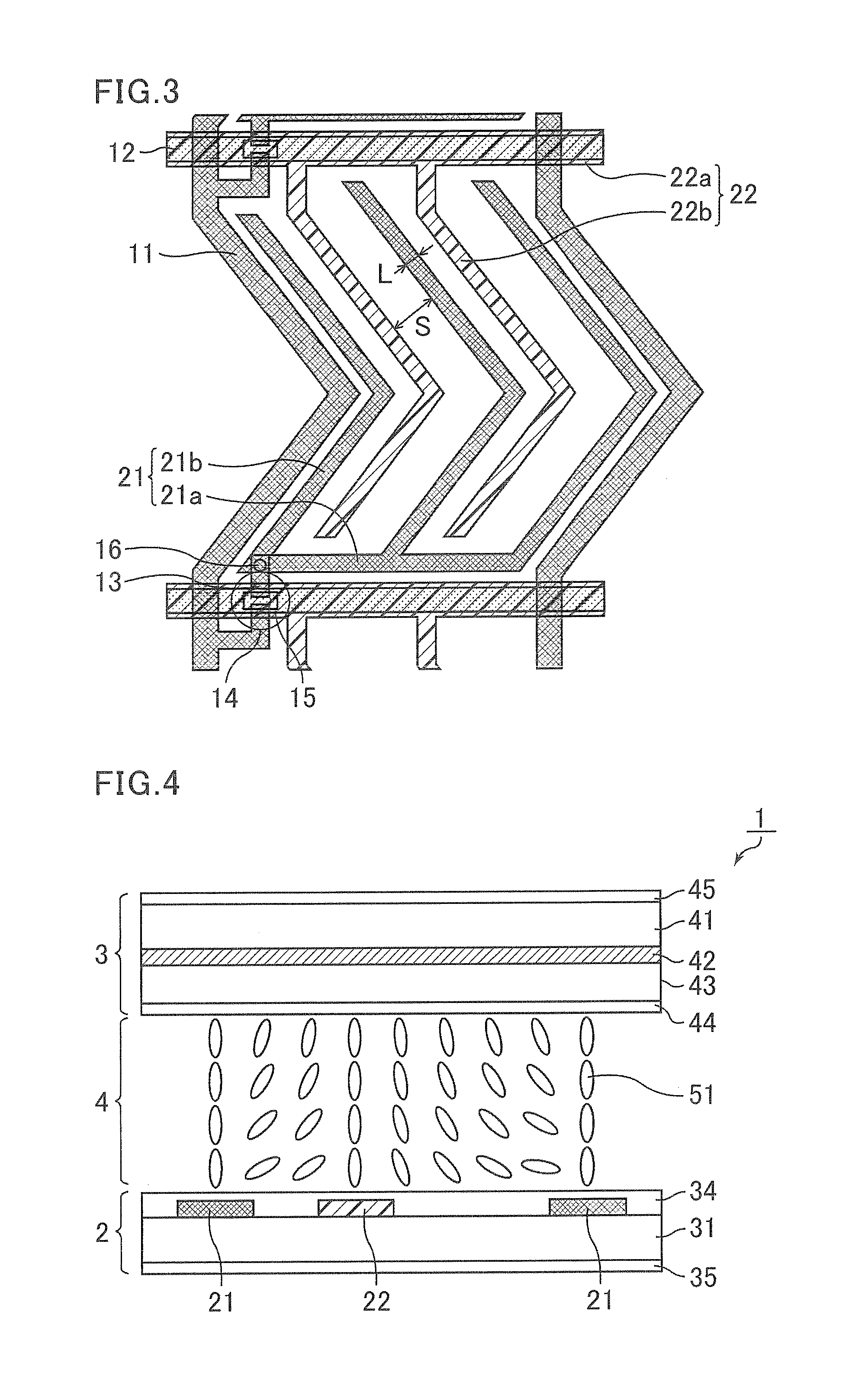
[0125]FIG. 3 is a plan view schematically illustrating a configuration per sub-pixel of a TFT substrate of an LCD panel in Embodiment 2. The LCD panel in Embodiment 2 is the same as that in Embodiment 1, except that the source line 11, the branched part 21b of the pixel electrode 21, and the branched part 22b of the common electrode 22 are each formed not in a linear pattern but in a V pattern per sub-pixel. Further, the source line 11, which is formed over a plurality of sub-pixels, forms a zig-zag pattern in the entire substrate plane. In Embodiment 2, the pair of polarizers is disposed such that the azimuths of their polarization axes are in the same relationship as in Embodiment 1, specifically, in parallel or orthogonal to the extending direction of the gate lines 12.

[0126]The above-mentioned V-shaped part has such a shape as extending two opposite directions from the line bisecting the longitudinal side of the sub-pixel, and the portion extending to one direction and the porti...

embodiment 3

[0127]The LCD panel of Embodiment 3 is a TBA-LCD panel where an electrode provided in a counter substrate as well as a pair of electrodes provided in the same substrate forms an electric field in an LC medium and the alignment of LC molecules whose initial alignment is vertical alignment is controlled, thereby controlling image display.

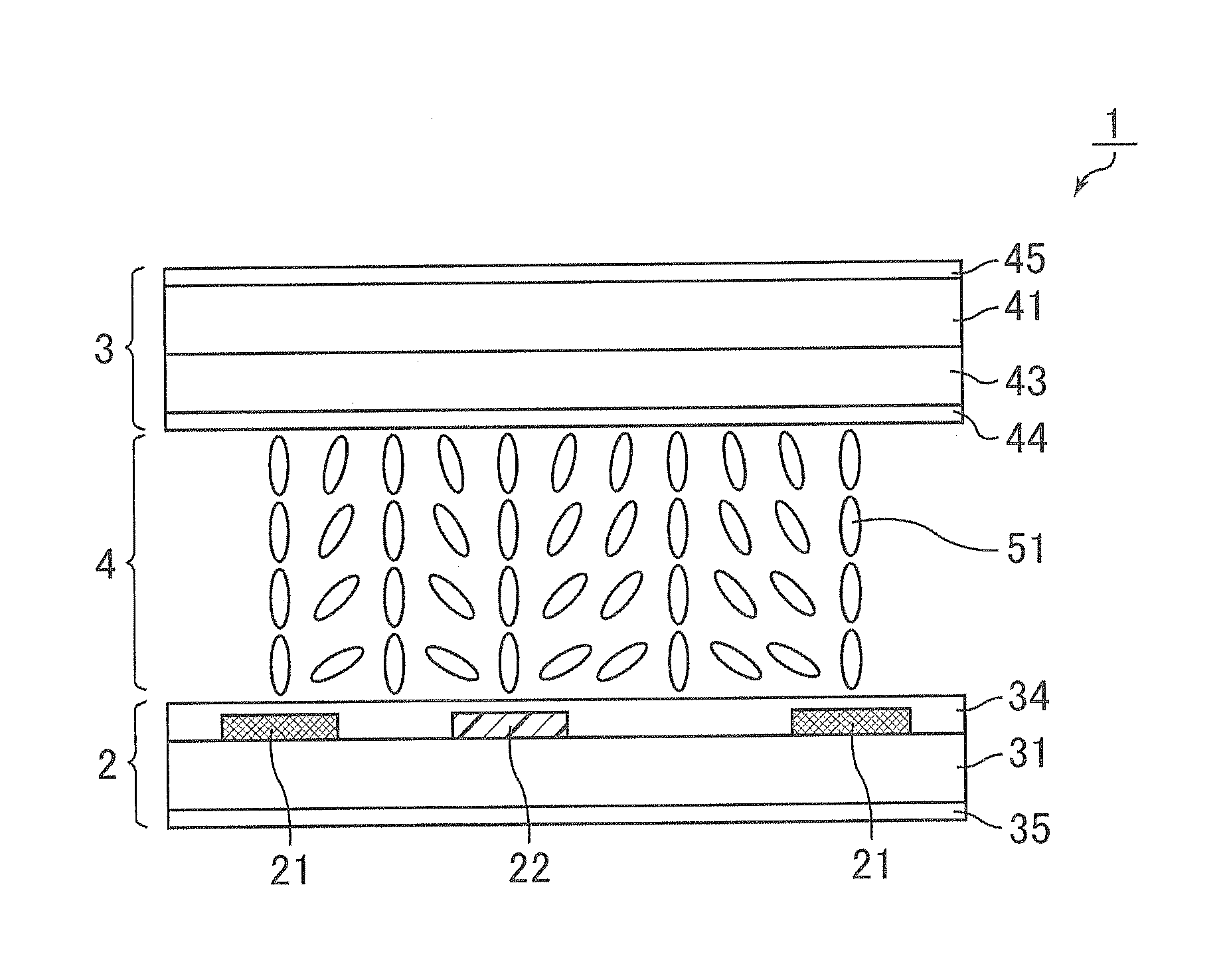
[0128]FIG. 4 is a cross-sectional view schematically illustrating a configuration of the LCD panel of Embodiment 3. As illustrated in FIG. 4, the LCD panel of Embodiment 3 includes a pair of substrates composed of a TFT substrate and a counter substrate. The LCD panel of Embodiment 3 is different from those of Embodiments 1 and 2 in that the panel includes a counter electrode (third electrode) 42 provided in the counter substrate 3. Specifically, as illustrated in FIG. 4, the counter substrate 3 in Embodiment 3 includes an insulating substrate 41, and further includes a counter electrode 42, an overcoat layer 43, and a vertical alignment film 44 stack...


PUM


Abstract

A TBA-liquid crystal display panel including a liquid crystal medium with positive dielectric anisotropy, wherein the liquid crystal medium includes, in 100% by weight of the liquid crystal compounds identified by the compounds recited in formulas I through IX below:
    • wherein,
    • R1, R3, R3*, R5, R6, R7, R8, and R9 independently denote C2-5 linear alkyl, preferably propyl or pentyl,
    • R2 denote C4-6 linear alkyl, preferably butyl or pentyl; and
    • R4 denotes C1-3 linear alkyl, preferably methyl.

Description

BACKGROUND OF THE INVENTION[0001]1. Field of the Invention[0002]The present invention relates to a liquid crystal display (LCD) panel including a liquid crystal (LC) medium with positive dielectric anisotropy (Δ∈).[0003]2. Discussion of the Background[0004]There is a great demand for LCDs, in particular of the matrix type, which have very high specific resistance at the same time as a large working-temperature range, short response times even at low temperatures and low threshold voltage. LC media are required which facilitate the following advantages in LC cells:[0005]extended nematic phase range (in particular down to low temperatures)[0006]the ability to switch at extremely low temperatures (outdoor use, automobile, avionics)[0007]increased resistance to UV radiation (longer service life).[0008]For LC cells, LC media are desired which enable greater multiplexability, lower threshold voltages and broader nematic phase ranges, in particular at low temperatures. A further widening o...

Claims


Application Information

Patent Timeline
IPC IPC(8): C09K19/00
CPCC09K19/3402C09K19/46C09K2019/0466C09K2019/124Y10T428/10C09K2019/3025C09K2019/3078C09K2019/3422C09K2019/3004C09K2323/00
Inventor MATSUMOTO, TOSHIHIROMURATA, MITSUHIROKAWAHIRA, YUICHIKANEHIRO, MASAYUKITAKEDA, TAKANORITANAKA, NORIHIROICHINOSE, HIDEO
Owner MERCK PATENT GMBH
Why Eureka
Try Eureka