Scintillating fiber dosimeter array

a fiber dosimeter and fiber array technology, applied in the field of dosimetry, can solve the problems of inability to use online assessment, affecting film response, and subject to drawbacks

Active Publication Date: 2012-05-22
UNIV LAVAL
View PDF12 Cites 15 Cited by
  • Summary
  • Abstract
  • Description
  • Claims
  • Application Information

AI Technical Summary

Benefits of technology

[0011]An optical connector may also be used for providing repeatable optical coupling between the collection optical fibers and the photo-detector. The photo-detector imager takes a two-dimensional image of the input optical signals. The connector may be such that it maintains the output ends of the collection optical fibers in a predetermined spatial relationship relative to one another, and connects to the photo-detector in such a way that the collection optical fibers have a precise location relative to the imager. In one embodiment, the connector maintains the collection optical fibers in an equally-spaced arrangement that minimizes optical crosstalk between the optical signals that are output from the fibers. Various arrangements of the collection optical fibers relative to the imager may be used, such that a correlation between the image taken by the photo-detector and the spatial distribution of the scintillating optical fiber detectors may be selected as desired by the user.
[0014]The calibration method allows proper determination of a gain coefficient for the dosimeter despite the presence of parasitic radiation such as {hacek over (C)}erenkov light resulting from irradiation of the collection fiber with the predetermined radiation type. Such non-scintillation radiation is generated in the entire spectral range but with different yield in each spectral window. The method may also be applied to a radiation dosimeter having multiple pairs of scintillating optical fibers and accompanying collection optical fibers and, when the scintillating / collection fiber pairs are similar construction, calibration of one may be applied to the others. That is, the calibration values determined during calibration of one of the scintillating / collection optical fiber pairs may be applied to each of the other scintillating / collection optical fiber pairs of the dosimeter. Moreover, the calibration method may be conducted with only one predetermined dose measurement.

Problems solved by technology

They are, however, subject to drawbacks.
The need to develop the films before reading makes their use for online assessment impossible.
Moreover, the development process affects the film response.
Radiographic films are also notorious for over-responding to low-energy photons and they are not water-equivalent.
Finally, the precision of a radiographic film used for dose measurement in the clinic is often limited to ±5%.
However, radiochromic films are temperature dependent and sensitive to ultraviolet light.
Achieving better than 5% reproducibility in routine fashion with radiochromic film is also challenging.
Because the materials used with current detector arrays are not water-equivalent (typically made of silicon or air), the use of such an array creates a perturbation in the particle fluence.
Moreover, the non-water equivalence of these detectors prevents the use of three-dimensional arrays with closely packed detectors.
The current detector arrays also suffer from other limitations depending on the type of detector in use.
For semiconductor detectors, there may be significant angular dependence and poor reproducibility for low dose fractions.
Thermoluminescent detectors (TLD) have also been used in groups to measure dose at different location simultaneously, but the need to read each one individually limits frequent use of a large number of TLDs.
However, most gels share a delicate fabrication process and require a time-consuming development process that makes them unsuitable for online measurements.

Method used


Image

  • Scintillating fiber dosimeter array
  • Scintillating fiber dosimeter array
  • Scintillating fiber dosimeter array

Examples


Embodiment Construction

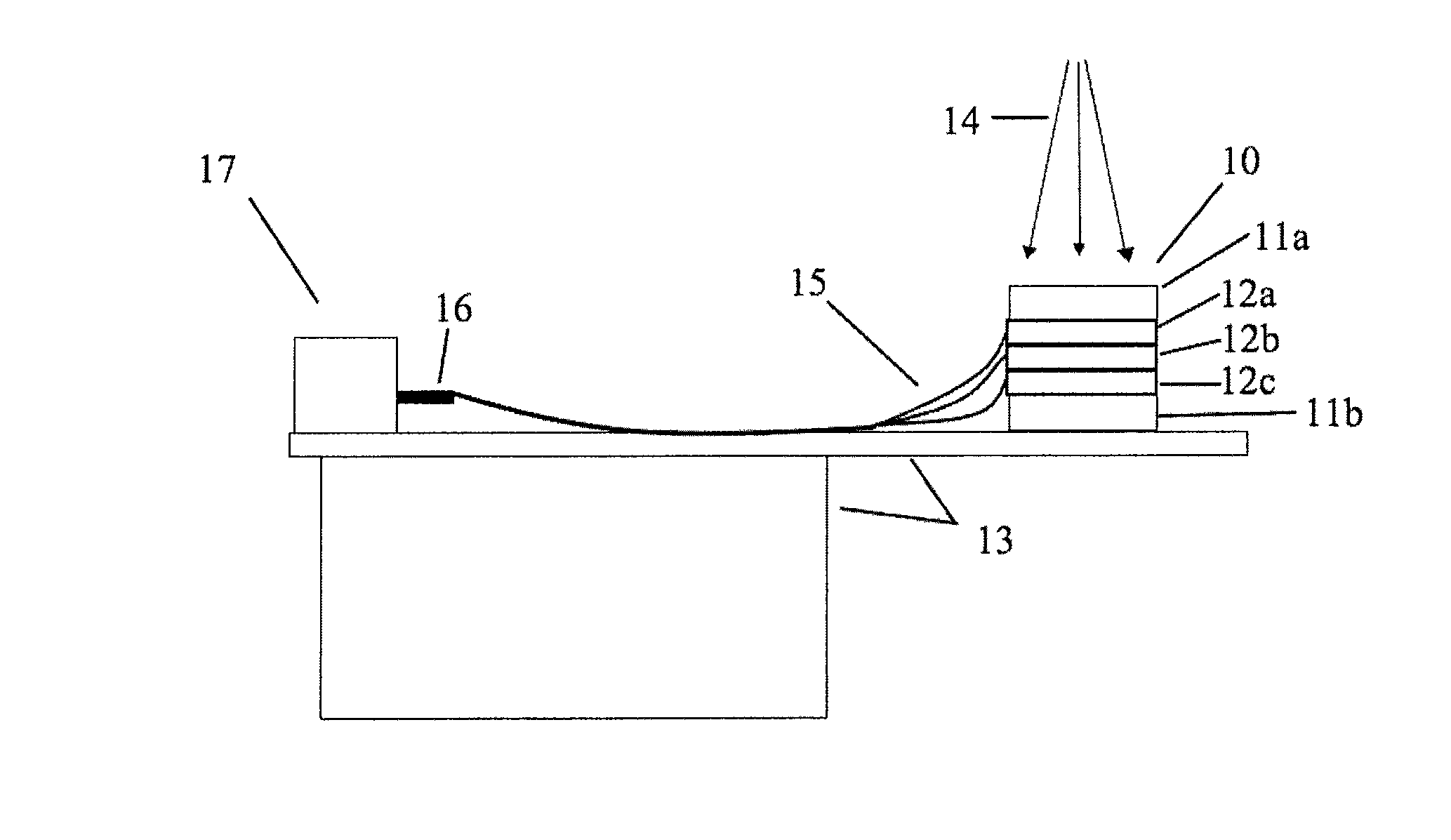
[0031]The present invention provides a dosimeter that makes use of scintillating optical fiber detectors. In an exemplary embodiment of the invention, miniature plastic scintillating fiber detectors are used that have a unique combination of properties. Their water equivalence is maintained over a broad energy range (e.g., 0.2 to 25 MeV). Furthermore, they provide a highly sensitive medium, which enables small sensitive volumes (e.g., less than 2 mm3) and high resolution, linearity to dose, dose rate independence, energy-independent response, and real-time readout.

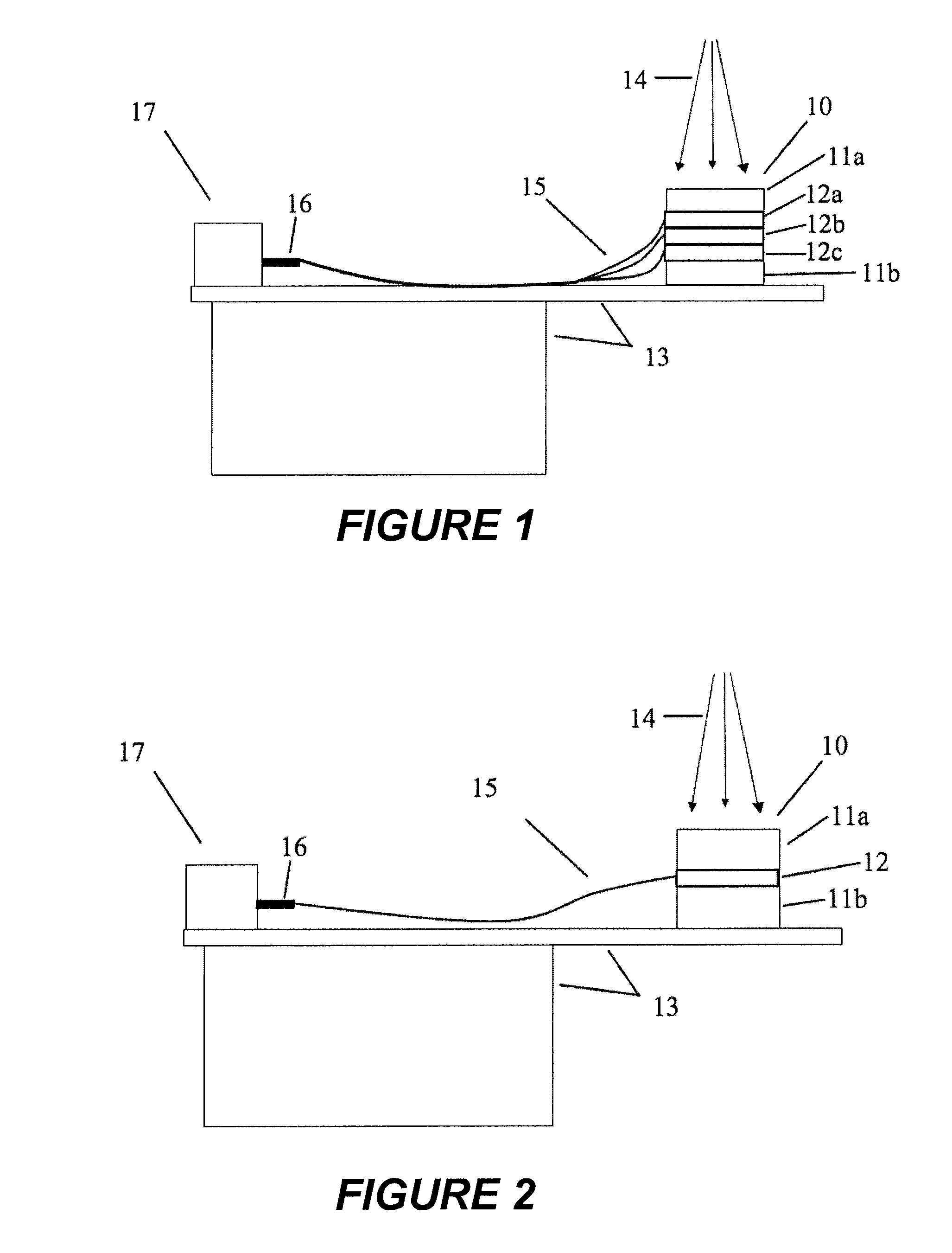
[0032]Shown in FIG. 1 is a scintillating fiber dosimeter array according to the present invention. The dosimeter is located on a radiotherapy treatment table 13, a phantom component 10 being composed of a series of water-equivalent modular slabs. Slabs 12a, 12b and 12c have scintillating fiber detectors embedded in them, while slabs 11a and 11b do not. While five slabs are shown in the embodiment of FIG. 1, those skilled i...


PUM


Abstract

A radiation dosimetry apparatus and method use a scintillating optical fiber array for detecting dose levels. The scintillating optical fiber detectors generate optical energy in response to a predetermined type of radiation, and are coupled to collection optical fibers that transmit the optical energy to a photo-detector for conversion to an electrical signal. The detectors may be embedded in one or more modular, water-equivalent phantom slabs. A repeatable connector couples the collection fibers to the photo-detector, maintaining the fiber ends in a predetermined spatial relationship. The detector fibers may be distributed as desired in a three-dimensional detection space, and may be oriented with their longitudinal axes at different orientations relative to a transmission axis of an incident radiation beam. A calibration method uses two measurements in two spectral windows, one with irradiation of the scintillator at a known dose and one with only irradiation of the collection fiber.

Description

FIELD OF THE INVENTION[0001]This invention relates generally to the field of dosimetry and, more particularly, to rapid, high-resolution dosimeters for advanced treatment technologies.BACKGROUND OF THE INVENTION[0002]Treatment modalities such as Intensity Modulated Radiotherapy (IMRT), helical tomotherapy and radiosurgery are pushing current dosimeter technologies to their limits. Two major driving forces are involved: 1) complex, two-dimensional field patterns encountered in IMRT and tomotherapy require high resolution (i.e., small volume) dosimeters that can be stacked or arrayed to provide a rapid but precise two- or three-dimensional dose measurement, which in turn requires that the dosimeters be water-equivalent in order not to disturb the fluence in the measurement plane and 2) small fields used in all three treatment modalities, down to 1×1 cm2 in IMRT and just a few millimeters in radiosurgery, give rise to volume effects such as spatial averaging in most dose detectors with...

Claims


Application Information

Patent Timeline
Patent Type & Authority Patents(United States)
IPC IPC(8): G01T1/02G01T1/26G01T1/24
CPCG01T1/02G01T1/201G02B6/4298G01T1/29
Inventor LACROIX, FREDERICBEAULIEU, LUCBEDDAR, SAMGUILLOT, MATHIEUGINGRAS, LUCARCHAMBAULT, LOUIS
Owner UNIV LAVAL
Why Eureka
Try Eureka