
Optical film, polarizing plate and image display device

a technology of optical film and polarizing plate, which is applied in the direction of polarizing elements, instruments, transportation and packaging, etc., can solve the problems of poor dispersion of fine particles, high scratch resistance, and whitening of coated films, and achieve excellent scratch resistance and anti-fouling durability.

Active Publication Date: 2012-05-29
FUJIFILM CORP
View PDF10 Cites 2 Cited by
  • Summary
  • Abstract
  • Description
  • Claims
  • Application Information

AI Technical Summary

Benefits of technology

[0012]One aspect of the present invention is to provide an antireflection film ensuring that when a low refractive index layer is formed using a fluorine-containing material and an inorganic fine particle, the refractive index is low, the scratch resistance and antifouling durability are excellent and whitening (white turbidity) due to aggregation of inorganic fine particles is reduced. Another aspect of the present invention is to provide a polarizing plate and an image display device each using the optical film.

Problems solved by technology

Also, the antireflection film is used on the outermost surface of a display and therefore, requires high scratch resistance.
However, in this case, dispersibility of the fine particle is bad and when the fine particle is added in a large amount, the coated film may be whitened, which is in need of improvement.
As regards this improvement, addition of a dispersant for the inorganic fine particle may be considered, but a normal dispersant tends to increase the refractive index and decrease the strength of the coated film.
However, this compound is a special compound using a fluorine-based solvent and cannot necessarily satisfy the scratch resistance, and an improvement is being demanded.

Method used


Image

  • Optical film, polarizing plate and image display device
  • Optical film, polarizing plate and image display device
  • Optical film, polarizing plate and image display device

Examples


examples

[0291]The present invention is described in greater detail below by referring to Examples, but the present invention should not be construed as being limited to these Examples. Unless otherwise indicated, the “parts” and “%” are on the mass basis.

(Preparation of Coating Solution (HCL-1) for Hardcoat Layer)

[0292]10 Parts by mass of cyclohexanone, 95 parts by mass of partially caprolactone-modified polyfunctional acrylate (DPCA-20, produced by Nippon Kayaku Co., Ltd.), and 5 parts by mass of a photopolymerization initiator (Irgacure 184, produced by Ciba Specialty Chemicals Corp.) were added to 90 parts by mass of methyl ethyl ketone (MEK). The resulting mixture was stirred and then filtered through a polypropylene-made filter having a pore size of 0.4 μm to prepare Coating Solution (HCL-1) for Hardcoat Layer.

(Production of Optical Film Sample 1)

[0293]A 80 μm-thick triacetyl cellulose film “TAC-TD80U” {produced by Fujifilm Corp.} in a roll form was unrolled, and Coating Solution (HCL-...


PUM

PropertyMeasurementUnit
sizeaaaaaaaaaa
thicknessaaaaaaaaaa
particle sizeaaaaaaaaaa

Abstract

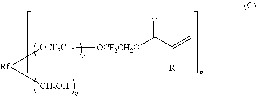
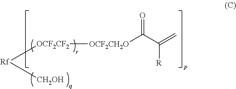
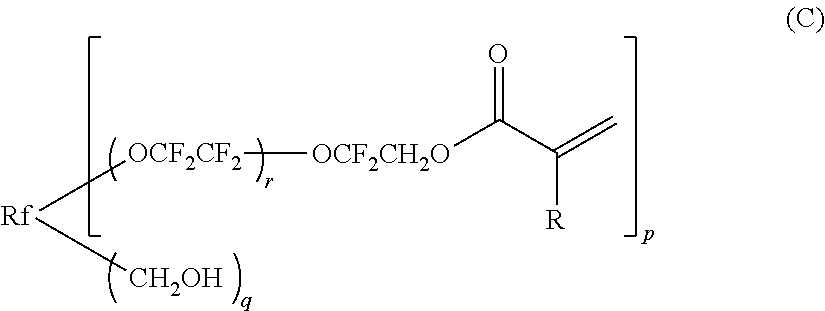
An optical film, includes: a transparent support; and at least one low refractive index layer, wherein the at least one low refractive index layer is a layer formed from a coating composition containing: (A) an inorganic fine particle; (B) a fluorine-containing copolymer; and (C) a polyfunctional fluorine-containing acrylate, and the polyfunctional fluorine-containing acrylate (C) is represented by the following structural formula:wherein Rf represents a (p+q)-valent perfluoro saturated hydrocarbon group having a carbon number of 1 to 20, which may have an ether bond; p represents an integer of 2 to 10; q represents an integer of 0 to 8, provided that (p+q) represents an integer of 2 to 10; r represents an integer of 0 to 100; and R represents a hydrogen atom, a methyl group, a fluorine atom or a trifluoromethyl group.

Description

BACKGROUND OF THE INVENTION[0001]1. Field of the Invention[0002]The present invention relates to an optical film, a polarizing plate using the optical film, and an image display device using the optical or polarizing plate on the outermost surface of the display.[0003]2. Description of the Related Art[0004]In an image display device such as cathode ray tube display (CRT), plasma display panel (PDP), electroluminescent display (ELD) and liquid crystal display (LCD), an antireflection film is generally disposed on the outermost surface of the display so as to reduce the reflectance by utilizing the principle of optical interference and thereby prevent the reduction in contrast due to reflection of outside light or prevent the disturbing reflection of an image.[0005]Such an antireflection film can be generally produced by forming, on a support, a low refractive index layer having a refractive index lower than that of the support to an appropriate film thickness. In order to realize a l...

Claims


Application Information

Patent Timeline
Patent Type & Authority Patents(United States)
IPC IPC(8): B32B5/16C08L67/00
CPCC09D127/12C09D133/16C08K5/103G02B5/30Y10T428/1036G02F2201/50G02F1/133502Y10T428/25C08L2666/28C09K2323/03
Inventor WAKIZAKA, DAIKIKATSUMATA, TAIJI
Owner FUJIFILM CORP
Learn More