Temperature regulating apparatus, exposure apparatus, and device manufacturing method
a technology of exposure apparatus and temperature regulation apparatus, which is applied in the direction of electric controllers, printers, instruments, etc., can solve the problems of fluctuation in the temperature of factory cooling water, power consumption tends to increase, and the overall heat transfer coefficient also changes
- Summary
- Abstract
- Description
- Claims
- Application Information
AI Technical Summary
Benefits of technology
Problems solved by technology
Method used
Image
Examples
first embodiment
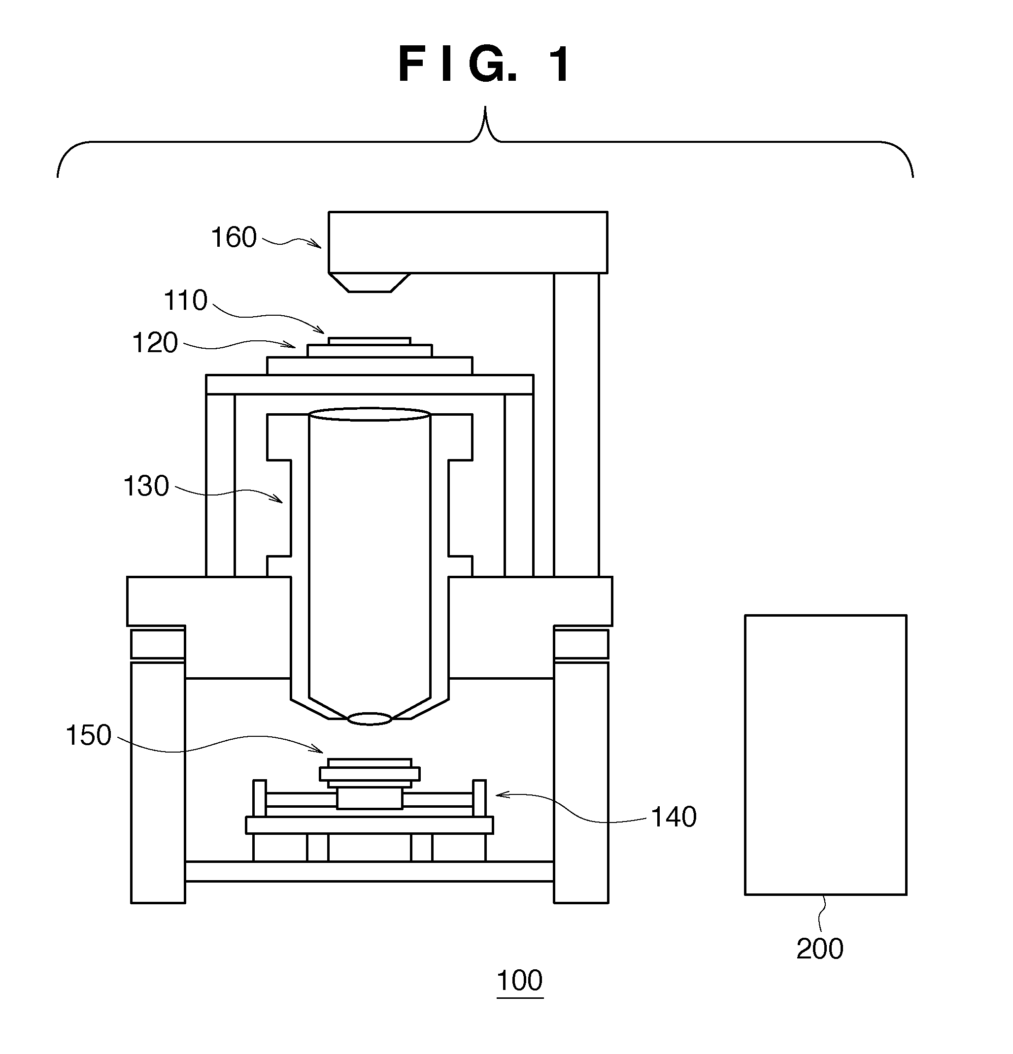
[0027]FIG. 1 is a view showing the schematic arrangement of an exposure apparatus according to a preferred embodiment of the present invention. An illumination optical system 160 illumines a reticle (mask) held by a reticle stage 120 with exposure light provided from a light source (not shown). A projection optical system 130 causes the exposure light transmitted through the reticle 110 to strike a wafer (substrate) 150 placed on a wafer stage 140, thereby forming an image of a pattern of the reticle 110 on the wafer 150. With this operation, the wafer 150 is exposed to light. As a light source, for example, a KrF laser or an ArF laser can be used.
[0028]In an exposure apparatus called a stepper, the reticle stage 120 stands still, and the wafer stage 140 stands still during exposure. When the exposure is complete, the wafer stage 140 is step-driven for exposure for the next shot. In an exposure apparatus called a scanning stepper, the reticle stage 120 and the wafer stage 140 are sy...
second embodiment
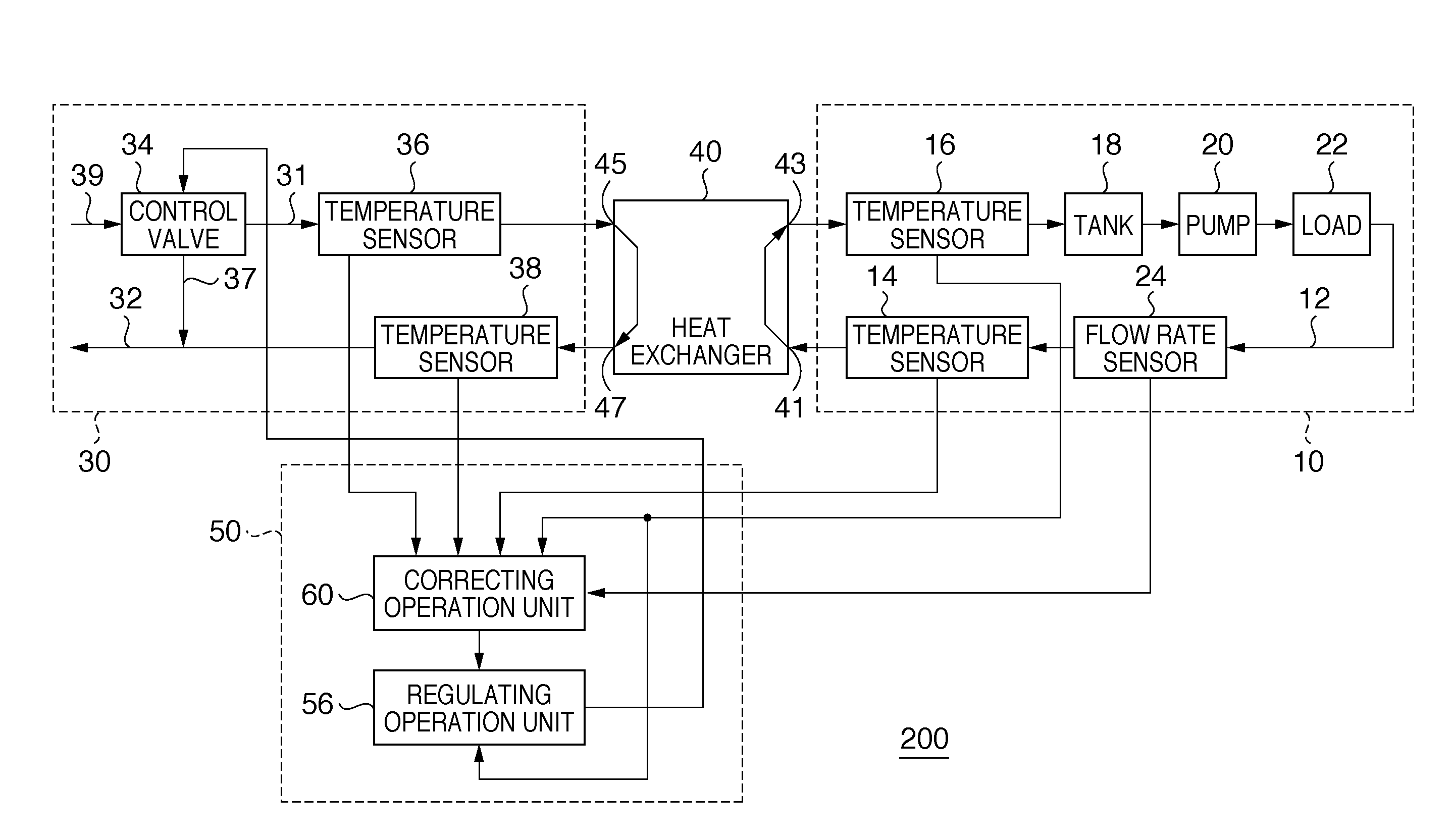
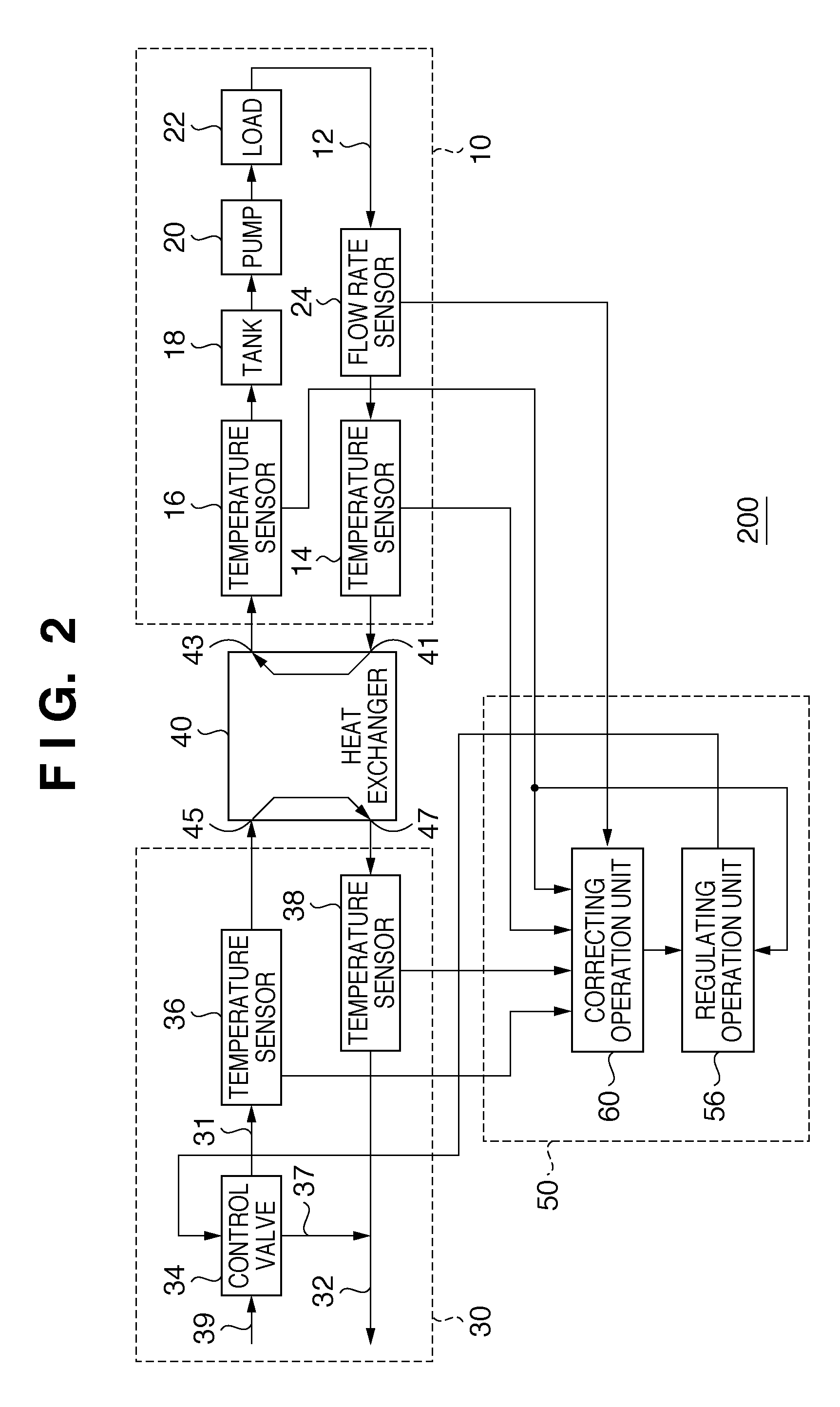
[0080]The second embodiment differs from the first embodiment in a control unit 50, more specifically, the arrangement in a regulating operation unit 56 of the control unit 50. More specifically, the second embodiment has an arrangement in which the control unit 50 shown in FIG. 6 is replaced with a control unit 50a shown in FIG. 7. The control unit 50a differs from the control unit 50 in that the regulating operation unit 56 (compensator 90) is replaced with a regulating operation unit 56a (compensator 90a). Note that things to which no reference is made can conform to the first embodiment.
[0081]In the second embodiment, the lag compensator 80 and the gain correcting unit 78 are arranged behind the adder 76. Operation in the lag compensator 80 and operation in the gain correcting unit 78 can be the same as those in the regulating operation unit 56.
[0082]According to the second embodiment, it is possible to accurately calculate the gain of the heat exchanger, which changes depending...
third embodiment
[0083]FIG. 8 is a graph showing the input / output characteristic of a control valve 34, that is, the relationship between the manipulated variable of the control valve 34 and the flow rate. In general, the input / output characteristic of the control valve 34 is often not linear, but nonlinear. Due to the nonlinear characteristic of the control valve 34, the gain represented by (Δ flow rate) / (Δ manipulated variable) changes. If, therefore, temperature regulation is performed without correction of the gain fluctuation of the control valve, the temperature stability will deteriorate.
[0084]The third embodiment differs from the first embodiment in the arrangement of the control unit. More specifically, the third embodiment has an arrangement in which the control unit 50 shown in FIG. 6 is replaced with a control unit 50b shown in FIG. 9. In this case, the control unit 50 differs from the control unit 50b in that the regulating operation unit 56 and the correcting operation unit 60 are repl...
PUM
 Abstract
Description
Claims
Application Information
 - R&D
- Intellectual Property
- Life Sciences
- Materials
- Tech Scout
- Unparalleled Data Quality
- Higher Quality Content
- 60% Fewer Hallucinations
Browse by: Latest US Patents, China's latest patents, Technical Efficacy Thesaurus, Application Domain, Technology Topic, Popular Technical Reports.
© 2025 PatSnap. All rights reserved.Legal|Privacy policy|Modern Slavery Act Transparency Statement|Sitemap|About US| Contact US: help@patsnap.com


