Tuning-fork type piezoelectric vibrating piece, piezoelectric frame, piezoelectric device, and a manufacturing method of tuning-fork type piezoelectric vibrating piece and piezoelectric frame
a manufacturing method and piezoelectric technology, applied in the direction of device details, device material selection, etc., can solve the problem that the weight of the respective parts may easily collide with each other, and achieve the effect of low frequency vibration and easy frequency adjustmen
- Summary
- Abstract
- Description
- Claims
- Application Information
AI Technical Summary
Benefits of technology
Problems solved by technology
Method used
Image
Examples
first embodiment
>
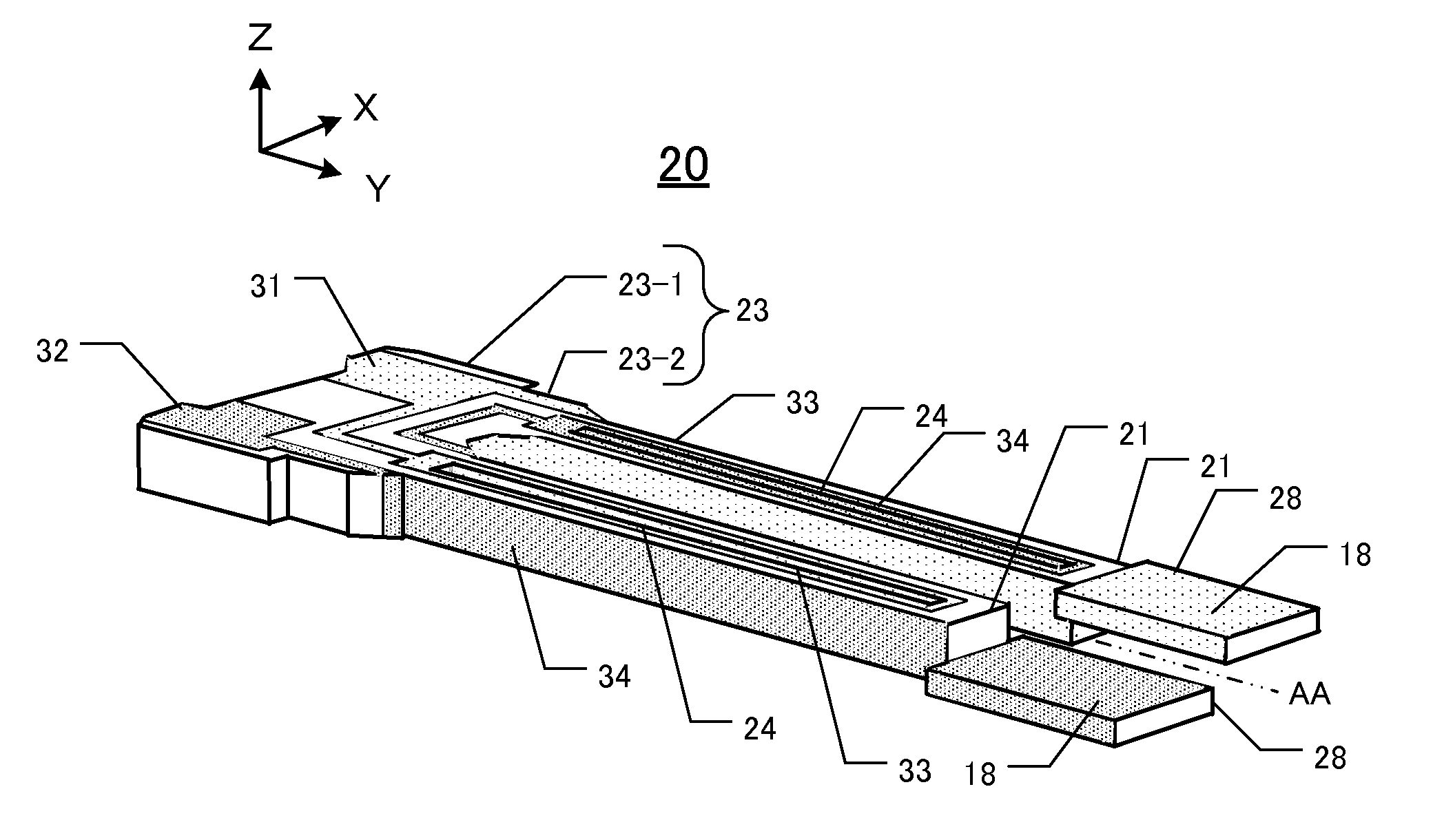
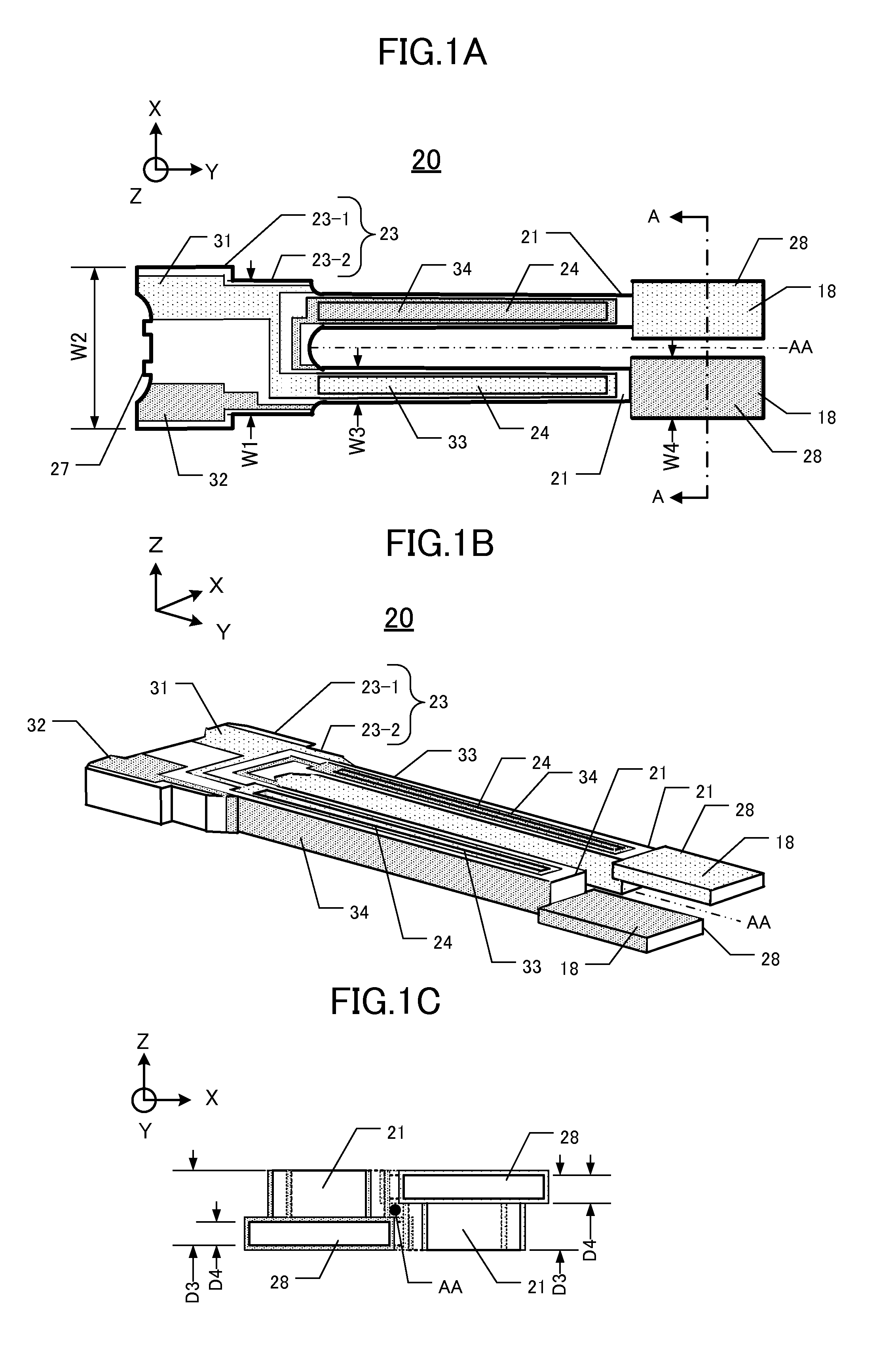
[0068]FIG. 1A is a top view of a first tuning-fork type crystal vibrating piece 20 of a first embodiment. FIG. 1B is a perspective view of FIG. 1A. FIG. 1C is a cross-sectional view along A-A line of a pair of weight portions of the first tuning-fork type crystal vibrating piece 20.
[0069]A base material of a first tuning-fork type crystal vibrating piece 20 is a Z-cut single crystal wafer. As shown in FIG. 1A, the first tuning-fork type crystal vibrating piece 20 comprises a base portion 23 having a first base portion 23-1 and a second base portion 23-2, and a pair of vibrating arms 21, which is biforked and extends with a designated width (W3) from the first base portion 23-1 in Y direction. The distal ends of vibrating arms are provided with a pair of weight portions 28. The base portion 23 has a pair of connecting portions 27 for attaching the first tuning-fork type crystal vibrating piece 20 to a single crystal wafer temporarily.
[0070]The tuning-fork type crystal vibrating piec...
first alternative example
>
[0083]FIG. 3A is a top view of a second tuning-fork type crystal vibrating piece 20A of a first alternative example. FIG. 3B is a perspective view of FIG. 3A. FIG. 3C is a cross-sectional view along C-C line of a pair of weight portions of the second tuning-fork type crystal vibrating piece 20A.
[0084]As shown in FIG. 3A, the weight portion 28 of the vibrating arms 21 of the second tuning-fork type crystal vibrating piece 20A is a hammer-head shape, and the width W4 and W5 are wider than the width (W3) of the vibrating arms 21. The weight portion 28 has two different widths, a width W4 and W5, in thickness direction (Z direction) and the width W5 is narrower than the width W4. One weight portion 28 has a skirt 28a formed on one surface side such that the cross-section is T-section. The width of the weight portion 28 with the skirt 28a is width W4 and the width of the weight portion 28 without the skirt 28a is width W5. The width of the skirt 28a is the widest dimension of the weight...
second alternative example
>
[0087]FIG. 4A is a top view of a third tuning-fork type crystal vibrating piece 20B of a second alternative example. FIG. 4B is a perspective view of FIG. 4A. FIG. 4C is a cross-sectional view along D-D line of a pair of weight portions of the third tuning-fork type crystal vibrating piece 20B.
[0088]As shown in FIG. 4A, the weight portion 28 of the vibrating arms 21 of the third tuning-fork type crystal vibrating piece 20B is a hammer-head shape, and the width W4 and W6 are wider than the width (W3) of the vibrating arms 21. The weight portion 28 has two different widths, a width W4 and W6, in thickness direction (Z direction) and the width W6 is narrower than the width W4. One weight portion 28 has a projection region 28b, which is formed in Y direction along one edge of inner side. The width of the weight portion 28 with the projection region 28b is a width W4 and its cross-section is an L-section. The cross-section of the other weight portion 28 is an inversed L-section.
[0089]As...
PUM
| Property | Measurement | Unit |
|---|---|---|
| thickness | aaaaa | aaaaa |
| width | aaaaa | aaaaa |
| weight | aaaaa | aaaaa |
Abstract
Description
Claims
Application Information
 - R&D
- Intellectual Property
- Life Sciences
- Materials
- Tech Scout
- Unparalleled Data Quality
- Higher Quality Content
- 60% Fewer Hallucinations
Browse by: Latest US Patents, China's latest patents, Technical Efficacy Thesaurus, Application Domain, Technology Topic, Popular Technical Reports.
© 2025 PatSnap. All rights reserved.Legal|Privacy policy|Modern Slavery Act Transparency Statement|Sitemap|About US| Contact US: help@patsnap.com


