Coherent optical signal processing

Inactive Publication Date: 2012-06-19
TEKTRONIX INC
View PDF21 Cites 14 Cited by
  • Summary
  • Abstract
  • Description
  • Claims
  • Application Information

AI Technical Summary

Benefits of technology

[0014]Beams used in differential detection are composed of interferometer terms for each polarization. A common path interferometer is advantageous in removing common-mode noise such as fluctuation in the total path length due to temperature variation (two outputs of a beam splitter create a balanced signal that can be detected with a balanced 
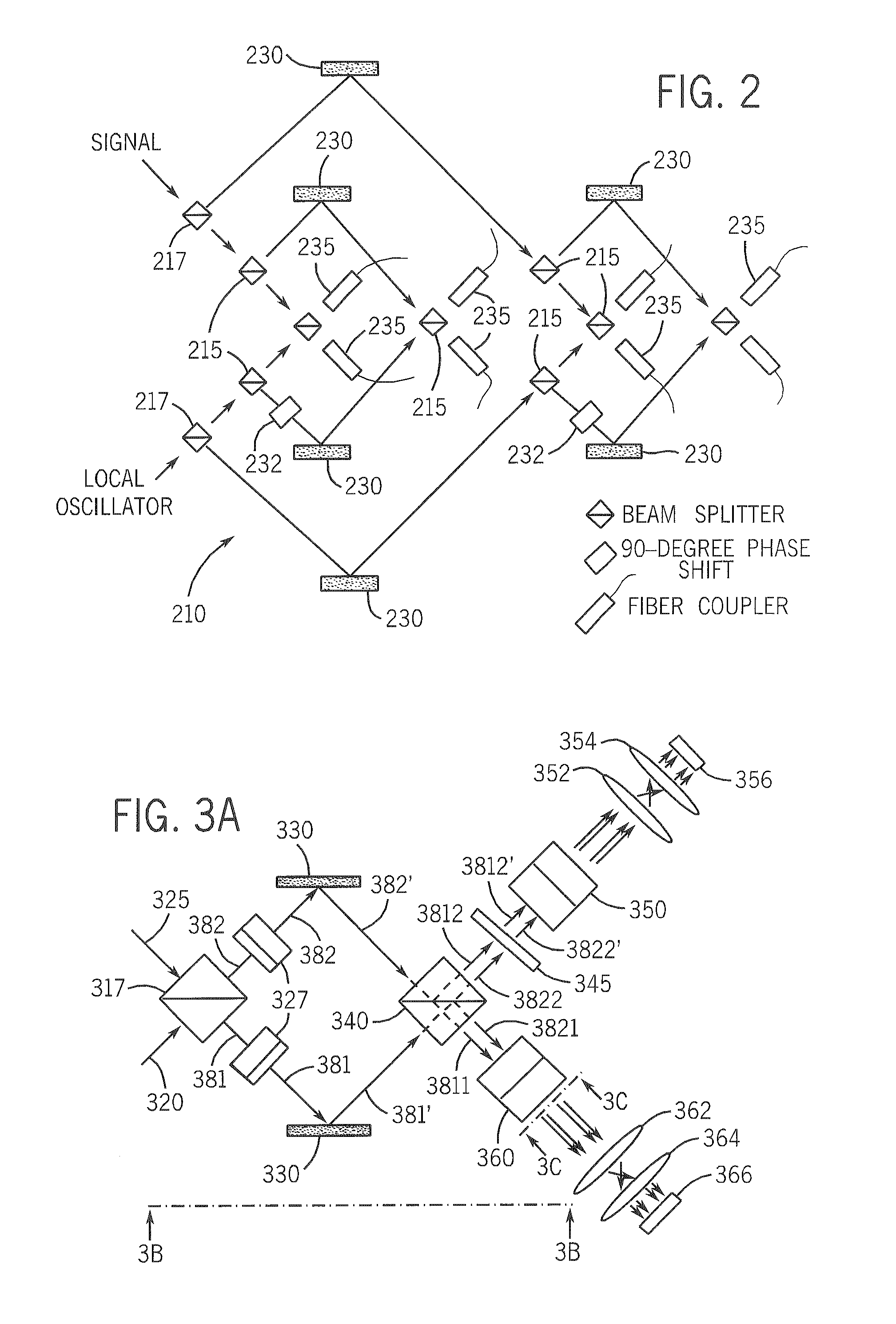
photodiode / receiver arrangement). Novel and non-obvious embodiments of a Savart device disclosed and claimed herein use two birefringent crystals (or plates) with optic axes oriented at 90° with respect to each other to equalize path length and generate the needed differential beams. This eliminates PBS cubes and other earlier devices that introduce difficult path-length matching of cube outputs that emerge at 90° angles and require optical elements to steer them back to the balanced detectors (a half-wave waveplate also is needed to keep the beams in the plane of the apparatus). The Savart device (also referred to as a Savart polariscope or Savart plate) generates two output beams both displaced laterally in two orthogonal directions from their input beam. Rotation of the Savart device by 45° eliminates the waveplate while maintaining horizontal beam separation, which is advantageous for vertically multiplexed beams if the goal is a square pattern. A benefit of the Savart device as a polarizer in a receiver is that spurious noise from optical reflections is eliminated. Moreover, a pair of input beams can be processed into four Savart device output beams for imaging onto a specialized photodetector array that utilizes close orientation of photodiodes for balanced detection.
[0015]Detection techniques and apparatus include novel and non-obvious embodiments in which photodiodes are incorporated into the optical assembly (for example, mounted to a chip, die, substrate or the like), thus removing intervening fiber connections and eliminating excess optical loss that otherwise occurs. In some embodiments, the photodiodes are included in the optical assembly, providing an additional degree of freedom since the detectors need not be designed for fiber coupling and allowing many more detectors and amplifiers to be incorporated onto one chip. Earlier coherent receiver designs required separate optical and detector assemblies, necessitating coupling in and out of single-mode fiber and resulting in a minimum of 0.2-dB of additional optical loss at each fiber interface due to the difficulty of perfectly mode-matching and anti-reflection-coating the fiber. Also, each of these earlier system fiber couplings added substantial cost due to ruggedizing the connection. Cost was multiplied when more high-frequency packages were required. Earlier system separation of the detector / receiver assembly from the optics also led to imperfect path matching, impacting noise rejection provided by balanced detection. A 30-dB rejection ratio requires amplitude response matching to 3% and path length matching to <1% of the symbol period (<1 ps for 10 Gbaud), matching nearly impossible with a separately packaged detector / receiver.
[0016]Using embodiments of the detection apparatus, beams can be simply imaged onto detectors arranged in any pattern that is convenient for the optical assembly and electrical design. Another advantage of imaging onto detectors is that detector spacing can be quite close, thereby reducing stray capacitance when detectors are coupled together to provide a balanced output. This is done while maintaining practical beam separation in the optics. In addition to reducing cost and optical loss, including detectors in the optical assembly and using telescopic imaging for photodiode coupling relaxes alignment tolerances by the telescope magnification. Unlike optical fiber, a photodiode is effective at receiving light from almost any angle in 2π steradians (earlier coherent receiver optical assemblies needed alignment at the output plane to a fraction of the fiber core diameter and a fraction of the acceptance angle). Embodiments of the new detection apparatus require alignment to about 50 microns.
[0017]In one specific embodiment, detectors are arranged in a square pattern to allow four beams to be readily imaged onto the detectors with a simple telescopic lens arrangement. The square pattern minimizes the lens clear-aperture needed and the detector die-size and simplifies access to the two outputs of the two pairs of diodes with outputs on opposite sides of the chip. Integrating the four detectors onto one chip provides precisely controllable detector locations that can be coupled to the optics without individual manipulation of each detector's coupling.

Problems solved by technology

Earlier coherent receiver designs required separate optical and detector assemblies, necessitating coupling in and out of single-mode fiber and resulting in a minimum of 0.2-dB of additional optical loss at each fiber interface due to the difficulty of perfectly mode-matching and anti-reflection-coating the fiber.
Also, each of these earlier system fiber couplings added substantial cost due to ruggedizing the connection.
Earlier system separation of the detector / receiver assembly from the optics also led to imperfect path matching, impacting noise rejection provided by balanced detection.

Method used


Image

  • Coherent optical signal processing
  • Coherent optical signal processing
  • Coherent optical signal processing

Examples


Embodiment Construction

[0055]The following detailed description will refer to one or more embodiments, but the present invention is not limited to such embodiments. Rather, the detailed description and any embodiment(s) presented are intended only to be illustrative. Those skilled in the art will readily appreciate that the detailed description given herein with respect to the Figures is provided for explanatory purposes as the invention extends beyond these limited embodiments.

[0056]Certain terms are used throughout the description and claims to refer to particular system components. In the following discussion and in the claims, the terms “including” and “comprising” are used in an open-ended fashion, and thus should be interpreted to mean “including, but not limited to . . . ” Phrases such as “coupled to” and “connected to” and the like are used herein to describe a connection between two devices, elements and / or components and are intended (unless otherwise restricted specifically) to mean physically,...


PUM


Abstract

Coherent optical signal processing is performed in a coherent receiver (or diagnostic / testing apparatus) that converts an amplitude and / or angle-modulated optical signal into two electrical signals. A simple receiver can only detect one phase of the signal and only the polarization that is aligned with a local oscillator laser polarization. To detect both phases and both polarizations, two sets of two interferometers, one each with a π / 2 phase shift are required. Coherent optical signal processing methods, apparatus, techniques, etc. are disclosed that include individual components comprising a polarization combiner, a Savart device and photodetection apparatus with substantially reduced temperature and alignment sensitivity operating in optical communication systems and / or subsystems. The various embodiments can be used alone or in such combinations to provide improved coherent optical signal processing in a receiver.

Description

CROSS-REFERENCE TO RELATED APPLICATIONS[0001]This application claims the benefit of priority under 35 U.S.C. §119(e) of the following:[0002]U.S. Provisional No. 61 / 039,952 filed on Mar. 27, 2008, entitled LOW-COMPONENT-COUNT COHERENT RECEIVER, the entire disclosure of which is incorporated herein by reference in its entirety for all purposes; and[0003]U.S. Provisional No. 61 / 105,750 filed on Oct. 15, 2008, entitled COHERENT OPTICAL SIGNAL PROCESSING, the entire disclosure of which is incorporated herein by reference in its entirety for all purposes.STATEMENT REGARDING FEDERALLY SPONSORED RESEARCH OR DEVELOPMENT[0004]Not applicable.REFERENCE TO SEQUENCE LISTING, A TABLE, OR A COMPUTER PROGRAM LISTING COMPACT DISK APPENDIX[0005]Not applicable.BACKGROUND[0006]1. Technical Field[0007]The present invention relates generally to optical communication and / or data transmission systems.[0008]2. Description of Related Art[0009]Optical communication systems transmit data using electromagnetic l...

Claims


Application Information

Patent Timeline
IPC IPC(8): H04J14/06H04B10/06H04B10/00
CPCH04B10/613H04B10/614G01S3/783
Inventor MARSLAND, JR., ROBERT A.DORRER, CHRISTOPHE J.
Owner TEKTRONIX INC
Why Eureka
Try Eureka