Multi-tubular fluid transfer conduit

a fluid transfer conduit and tubular technology, applied in the direction of branching pipes, combustion types, lighting and heating apparatuses, etc., can solve the problems of mechanical stress, structural failure of the conduit, thermal expansion, etc., and achieve the effect of better thermal insulation properties and better accommodative structural stresses

Active Publication Date: 2012-06-26
WOODWARD GOVERNOR CO
View PDF23 Cites 14 Cited by
  • Summary
  • Abstract
  • Description
  • Claims
  • Application Information

AI Technical Summary

Benefits of technology

[0007]In view of the above, embodiments of the present invention provide a new and improved fluid transfer conduit that overcomes one or more of the challenges existing in the art. More particularly, embodiments of the present invention provide a new and improved fluid transfer conduit including multiple nested concentric tubes that has better thermal insulation properties and can better accommodate structural stresses than conventional single tube fluid transfer devices.
[0011]In another aspect, an embodiment of the invention provides a method of reducing an axial stress induced on a fluid transfer conduit including forming a fluid transfer conduit and joining the fluid transfer conduit to a fluid transfer system. The fluid transfer conduit is formed to include multiple concentric tubes nested about an axis, wherein each of the concentric tubes has an upstream end and a downstream end. Each of the concentric tubes is joined with an adjacent tube at one of the upstream or downstream ends, wherein a fluid passageway is formed. The fluid transfer conduit is formed to further include a first connector and a second connector on opposite ends of the fluid transfer conduit, wherein the first connector and the second connector are attached to a structural support of the fluid transfer system.

Problems solved by technology

Frequently, a fluid transfer device, such as a tubular conduit, is subjected to mechanical stresses such as thermal expansion due to external forces.
Often an excessive amount of such stresses leads to a structural failure of the conduit.
Further, in some applications, heat transfer between fluid flowing through the conduit and the surrounding environment can be problematic.
For example, insulating a steam pipe to reduce heat loss of steam as it flows through the conduit has been a challenge.
Due to severe operating conditions within gas turbine engines, the engine's fuel nozzles are required to satisfy numerous design challenges.
One such challenge posed by severe external pressures and temperatures of hot compressor discharge air surrounding the exterior of the fuel nozzle is accommodation of large thermally induced deformations within the body of the fuel nozzle.
Unfortunately, a conventional fuel transfer conduit of the fuel nozzle comprising a single tube can experience a high thermal stress in such severe operating conditions, which results in structural failures.
Another challenge is thermally shielding fuel from the severe external temperatures.
If too much heat is transferred to fuel, fuel can begin to coke, thereby ruining or reducing the quality and delivery of fuel.
However, the evolution of the gas turbine engines has been such that temperature and pressure of the compressor discharge air have substantially risen, and thus, the thermal shielding of fuel has become even more of a design challenge.
For many applications, it has been found that the conventional single insulating fuel gap filled with the air-fuel-coke mixture does not provide enough thermal protection to fuel that the engine manufacturers require.

Method used


Image

  • Multi-tubular fluid transfer conduit
  • Multi-tubular fluid transfer conduit
  • Multi-tubular fluid transfer conduit

Examples


Embodiment Construction

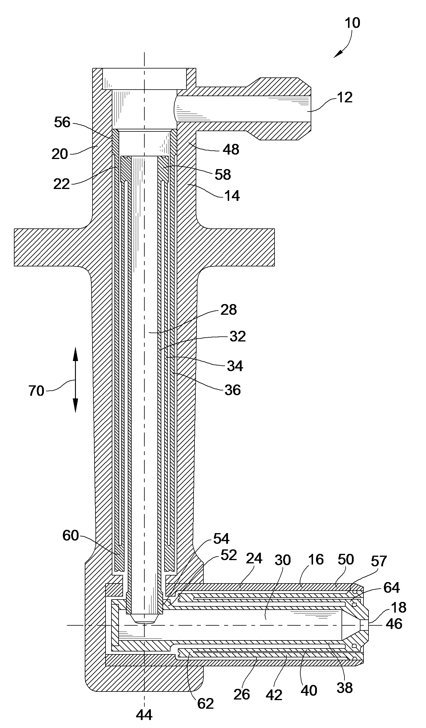
[0034]FIG. 1 shows a cross sectional view of a fuel nozzle 10 including a fuel transfer conduit 22 according to an embodiment of the present invention. The fuel nozzle 10 can be implemented in a gas turbine system to inject fuel into a combustion chamber, wherein fuel is mixed with air and burned at high temperatures while maintaining a near static pressure. The gas temperature required in a turbine varies according to engine speed, so the combustion chamber must be capable of a stable and efficient combustion over a wide range of operating conditions that can be maintained for extended periods. The temperature of air leaving a primary combustion zone can be approximately 1800° C. and 2000° C. The fuel nozzle 10 includes an improved fuel transfer conduit 22, which can better accommodate thermally induced structural stresses and better shield fuel from the severe temperatures of the gas turbine system.

[0035]Although the fuel transfer conduit 22 in this embodiment is used in the fuel ...


PUM


Abstract

A fluid transfer system having improved stress accommodation properties and thermal insulation properties is provided. The fluid transfer system includes a fluid transfer conduit comprising a plurality of concentric tubes configured to divide and distribute an axial stress induced in the fluid transfer conduit to each of the tubes and a vacuum cavity between the fluid transfer conduit and a structural support of the fluid transfer system to insulate fluid from a surrounding environment.

Description

FIELD OF THE INVENTION[0001]This invention generally relates to a fluid transfer device, more particularly a fluid transfer conduit configured for efficient thermal insulation and to accommodate structural stresses.BACKGROUND OF THE INVENTION[0002]Frequently, a fluid transfer device, such as a tubular conduit, is subjected to mechanical stresses such as thermal expansion due to external forces. In a tubular conduit structure, pulling along the tube axis at the ends of the tubular conduit that results from thermal expansion causes tensile stresses in the conduit structure, while pushing causes compressive stresses. Often an excessive amount of such stresses leads to a structural failure of the conduit. Further, in some applications, heat transfer between fluid flowing through the conduit and the surrounding environment can be problematic. For example, insulating a steam pipe to reduce heat loss of steam as it flows through the conduit has been a challenge.[0003]A fluid transfer condu...

Claims


Application Information

Patent Timeline
Patent Type & Authority Patents(United States)
IPC IPC(8): F16L11/00A62C5/02
CPCF16L9/18F16L9/19F23R3/283F23D14/78F23D14/76
Inventor LEE, FEI PHILIPWORTHINGTON, RALPH J.
Owner WOODWARD GOVERNOR CO
Why Eureka
Try Eureka