Atomic magnetometer

a magnetometer and atomic technology, applied in the field of magnetometers, can solve the problems of expensive cryogenic cooling and achieve the effect of improving the signal-to-noise ratio

Active Publication Date: 2012-07-03
NAT TECH & ENG SOLUTIONS OF SANDIA LLC
View PDF13 Cites 153 Cited by
  • Summary
  • Abstract
  • Description
  • Claims
  • Application Information

AI Technical Summary

Benefits of technology

[0017]One or more sets of magnetic coils can be located about the cell containing the alkali metal vapor. These magnetic coils can be used to substantia...

Problems solved by technology

Conventional superconducting magnetometers based on superconducting quantum interference devices (SQUIDs)...

Method used


Image

  • Atomic magnetometer
  • Atomic magnetometer
  • Atomic magnetometer

Examples


Embodiment Construction

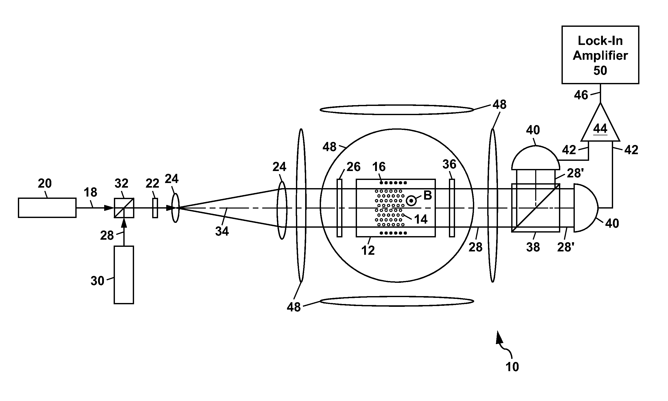
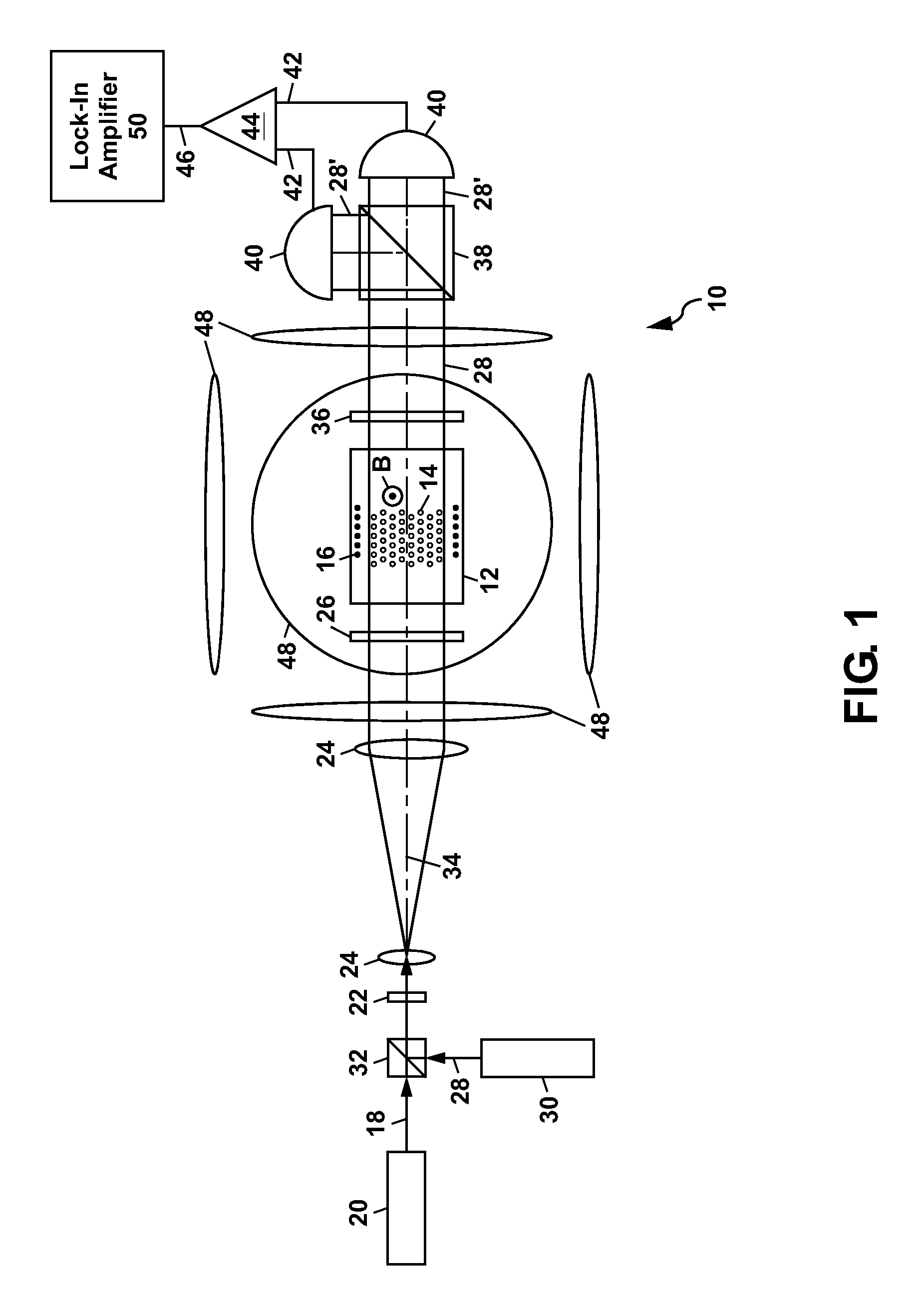
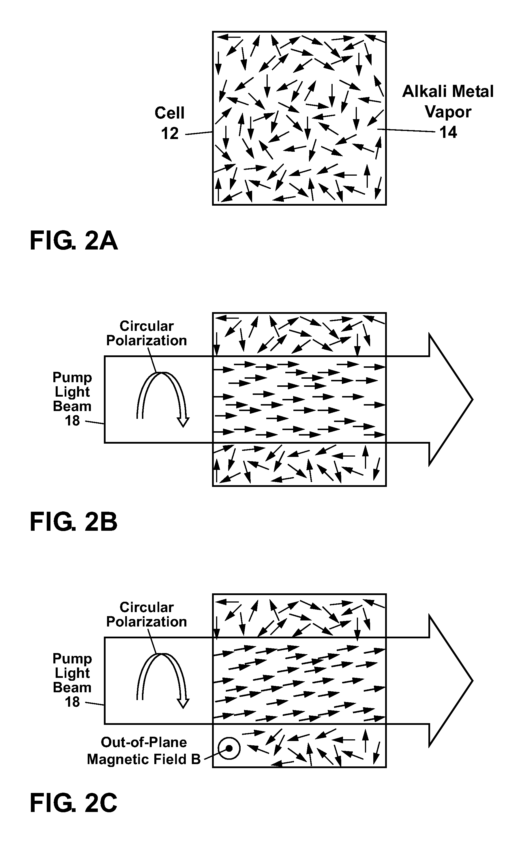
[0041]FIG. 1 shows a schematic diagram of a first example of an atomic magnetometer 10 for sensing a magnetic field according to the present invention. This apparatus 10, which is also referred to herein as a magnetometer 10, comprises a cell 12 containing an alkali metal vapor 14. The cell 12, which can be made of glass, can also include a buffer gas 16 (e.g. comprising a noble gas such as helium or neon). Another gas such as nitrogen can also be added to the buffer gas 16. The cell 12 can be heated to a elevated temperature to provide a density of alkali metal atoms in the vapor 14 which can range from about 1011 cm−3 to 1015 cm−3 or more. The exact temperature to which the cell 12 is heated will depend, in general, upon the alkali metal (e.g. sodium, potassium, rubidium, or cesium) which is used in the apparatus 10. As an example, when the alkali metal comprises rubidium-87, the cell 12 can be heated up to about 200° C. The cell 12 can be heated by locating the cell 12 within an ...


PUM


Abstract

An atomic magnetometer is disclosed which uses a pump light beam at a D1 or D2 transition of an alkali metal vapor to magnetically polarize the vapor in a heated cell, and a probe light beam at a different D2 or D1 transition to sense the magnetic field via a polarization rotation of the probe light beam. The pump and probe light beams are both directed along substantially the same optical path through an optical waveplate and through the heated cell to an optical filter which blocks the pump light beam while transmitting the probe light beam to one or more photodetectors which generate electrical signals to sense the magnetic field. The optical waveplate functions as a quarter waveplate to circularly polarize the pump light beam, and as a half waveplate to maintain the probe light beam linearly polarized.

Description

GOVERNMENT RIGHTS[0001]This invention was made with Government support under Contract No. DE-AC04-94AL85000 awarded by the U.S. Department of Energy. The Government has certain rights in the invention.CROSS REFERENCE TO RELATED APPLICATIONS[0002]The present application is related to U.S. patent application Ser. No. 12 / 173,547, entitled “Tuned Optical Cavity Magnetometer,” of common assignee filed on Jul. 15, 2008, the contents of which are incorporated herein by reference in their entirety.FIELD OF THE INVENTION[0003]The present invention relates in general to magnetometers, and in particular to atomic magnetometers which rely on optically polarizing an alkali metal vapor and optically probing the state of magnetization of the polarized alkali metal atoms to sense a magnetic field.BACKGROUND OF THE INVENTION[0004]High sensitivity detection of magnetic fields is critical to many applications including ordinance detection, geophysical mapping, navigation, and the detection of bio-magn...

Claims


Application Information

Patent Timeline
IPC IPC(8): G01V3/00
CPCG01R33/26
Inventor SCHWINDT, PETERJOHNSON, CORT N.
Owner NAT TECH & ENG SOLUTIONS OF SANDIA LLC
Why Eureka
Try Eureka