

Method for manufacturing semiconductor device or apparatus, and apparatus for manufacturing the same
a manufacturing method and semiconductor technology, applied in semiconductor/solid-state device testing/measurement, instruments, therapy, etc., can solve the problems of reduced yield, image distortion, and reduced yield, and achieve the effect of long time and optimal time during manufacturing
- Summary
- Abstract
- Description
- Claims
- Application Information
AI Technical Summary
Benefits of technology
Problems solved by technology
Method used
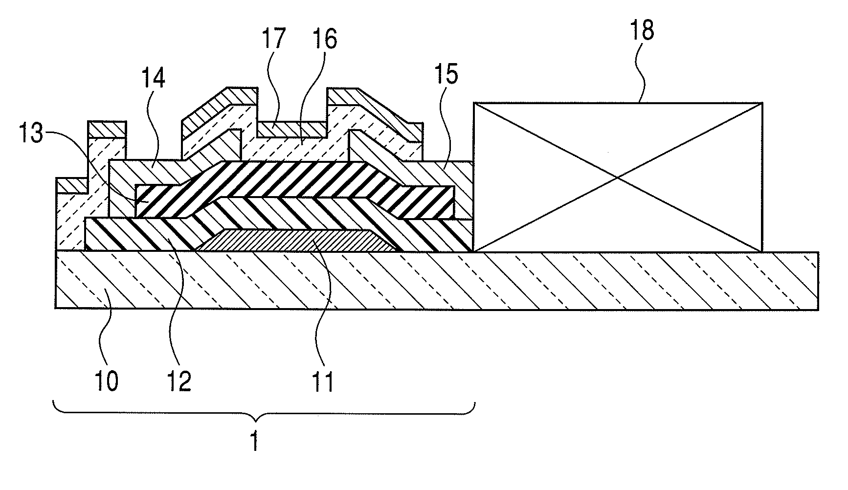
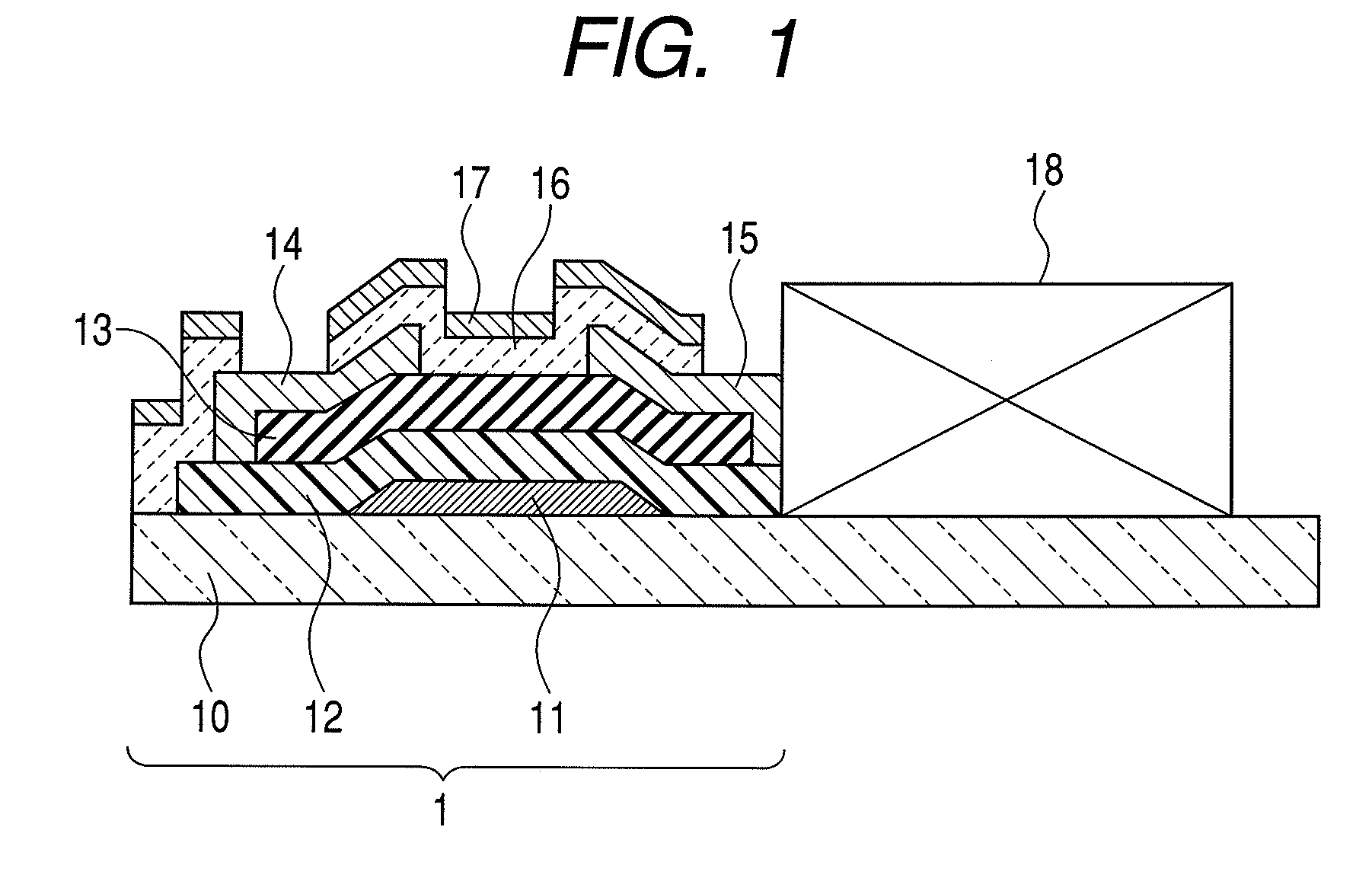
Image

Examples
example 1
[0061]In this example, an organic EL display device using a-IGZO for a channel layer was fabricated according to the method for manufacturing a semiconductor device and a semiconductor apparatus according to the present invention. In this example, an organic EL device driven at −10 to 30 V was used.
[0062]First, the absorption edge wavelength of a-IGZO was estimated.
[0063]20 nm of an a-IGZO film was formed on an n+-silicon wafer substrate with a thermally oxidized silicon film (film thickness: 100 nm) by a sputtering method. Here, the input RF power was 200 W. Also, for the atmosphere during film formation, the total pressure was 0.5 Pa, and the gas flow ratio at the time was Ar: O2=95:5. Also, the film formation rate was 8 nm / minute, and the substrate temperature was 25° C.
[0064]Next, the phase difference and amplitude ratio of reflected p- and s-polarized light were obtained by ultraviolet-visible spectroscopic ellipsometry. Further, assuming Tauc-Lorentz model absorption and Gauss...
PUM
 Abstract
Description
Claims
Application Information