Cleaning member, charging device, process cartridge, and image forming apparatus

a technology of image forming apparatus and charging device, which is applied in the direction of vehicle cleaning, corona discharge, instruments, etc., can solve the problems of contaminant imprinting, reduced chargeability, and inability to completely eliminate the difference in linear velocity between the two, so as to improve the cleaning

Inactive Publication Date: 2012-07-10
RICOH KK
View PDF36 Cites 5 Cited by
  • Summary
  • Abstract
  • Description
  • Claims
  • Application Information

AI Technical Summary

Benefits of technology

[0025]An object of the present invention is to solve the above problems caused in conventional cleaning units and cleaning devices, and to provide a cleaning member which can avoid the imprinting of a contaminant so as to enhance cleanability.
[0026]Moreover, another object of the present invention is to provide a charging device, in which the chargeability may not be decreased due to cleaning failure, a process cartridge and an image forming apparatus, in which abnormal images may not be formed.
[0027]Furthermore, still another object of the present invention is to provide a cleaning roller which can obtain excellent cleanability with respect to a roller member, a charging device equipped with the cleaning roller, a process unit, and an image forming apparatus.

Problems solved by technology

The charging roller is contaminated by a small amount of a toner and lubricant passing through the cleaning unit for photoconductor, and its chargeability is decreased over time.
However, when the linear velocity of the charging roller to be cleaned and that of the cleaning member differ in a contact portion, the contaminant may be imprinted on a surface of the charging roller.
However, as both of them substantially vary in outer diameter (component tolerance), the difference in linear velocity therebetween cannot be completely eliminated.
Therefore, a contaminant may be imprinted on the surface of the charging roller.
However, corona products such as ozone, nitrogen oxide and the like are generated by the corona discharge, causing environmental contamination.
Moreover a nitric acid compound (ammonium nitrate) produced from a nitrogen oxide adheres to the charging devices, adversely affecting the chargeability.
However, a toner or paper powder remaining on the latent image bearing member surface after the cleaning step tends to adhere onto the charging roller.
As a result, the latent image bearing member cannot be uniformly charged.
On the other hand, the technique has a disadvantage that the drive transmission is not kept stable and that the charging roller slips because the cleaning roller is driven by a frictional force between the charging roller and the cleaning roller.
However, there is a disadvantage that a linear pressure (nip width) varies depending on a variation of the roller diameter and change over time, because the distance between the axis of the charging roller and the axis of the cleaning roller is necessary to be fixed.
When the latent image bearing member surface is abraded due to the pulse discharge of the charging roller, the thickness of a photosensitive layer on the latent image bearing member surface is decreased, i.e. film thickness loss is caused, adversely affecting the chargeability.
As a result, image quality may degrade.
In these cases, filming occurs on the charging roller, inhibiting the longer operating life of the charging roller.

Method used


Image

  • Cleaning member, charging device, process cartridge, and image forming apparatus
  • Cleaning member, charging device, process cartridge, and image forming apparatus
  • Cleaning member, charging device, process cartridge, and image forming apparatus

Examples


first embodiment -

-First Embodiment-

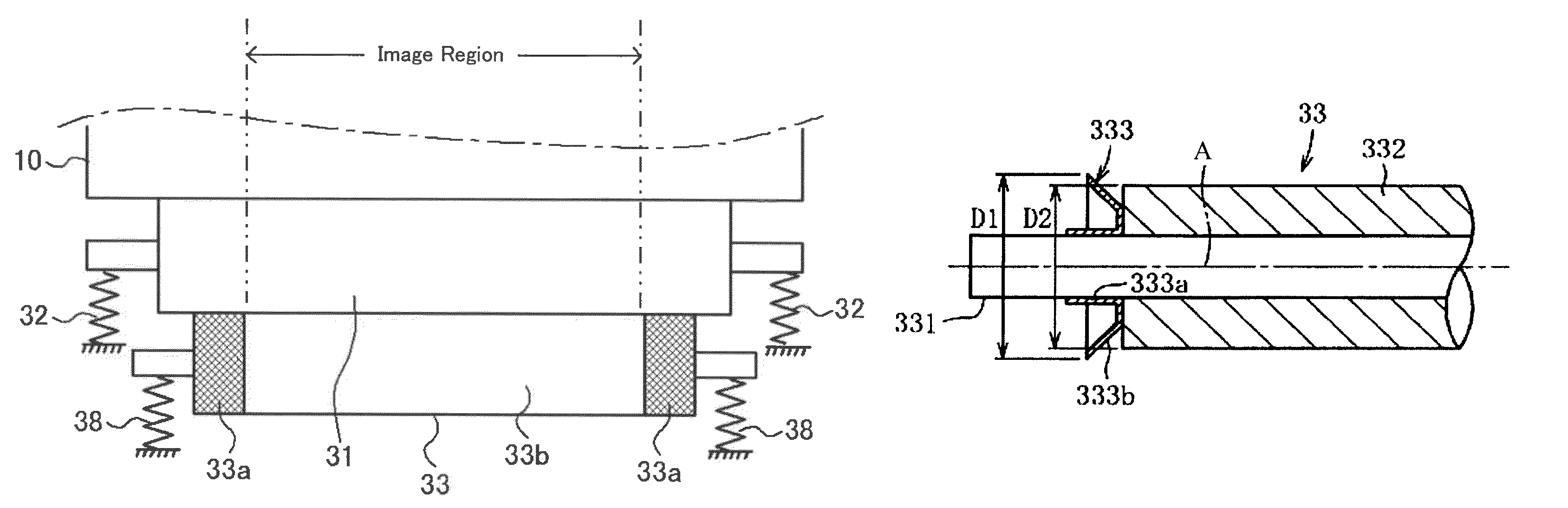
[0103]FIG. 5 is a side view schematically showing a contact portion between a photoconductor 10 and a charging unit.

[0104]As shown in FIG. 5, a charging roller 31 is biased to be in contact with the photoconductor drum 10 by a spring 32 practically via a bearing, and a charging roller-cleaning roller 33 is also biased to be in contact with the charging roller 31 by a spring member 38.

[0105]A charging roller-cleaning roller 33 of the first embodiment is formed in such a manner that a foam containing a melamine compound is formed into an elastic layer in a cylindrical shape on a core bar member, and a resin or the like attached on the foam by dipping or spray coating so as to provide high-friction coefficient parts 33a on the both ends. A central part in which the high-friction coefficient parts 33a are not provided is a cleaning part 33b formed of the foam. The friction coefficient of surfaces of the high-friction coefficient parts 33a are greater than that of a sur...

second embodiment -

-Second Embodiment-

[0107]FIG. 6 shows a second embodiment of the configuration of the charging roller. A charging roller 31B shown in FIG. 6 has spacer members 34 on both ends of the roller so as to form a charge gap (minute gap) G between a charging roller 31B and a photoconductor 10. A charging roller-cleaning roller 33 in the figure is the same as the charging roller-cleaning roller of FIG. 5, in which high-friction coefficient parts 33a are provided in a region other than an image formation region (a non-image region). Thus, the charging roller-cleaning roller 33 can be rotated according to the rotation of the charging roller in a system including the charge gap (minute gap), without substantially causing a difference in linear velocity. Therefore, a contaminant is not imprinted, and the surface of the roller member to be cleaned can be sufficiently cleaned.

third embodiment -

-Third Embodiment-

[0108]FIG. 7 shows a third embodiment of the cleaning member, which is a charging roller-cleaning roller in a system including a charge gap (minute gap).

[0109]A charging roller 31B shown in FIG. 7 is the same as that of FIG. 6. However, a charging roller-cleaning roller 133 of the third embodiment extends its length in a direction of a roller axis so long enough to be in contact with spacer members 34 on both ends of the charging roller 31B. Then, high-friction coefficient parts 133a are provided on both ends of the charging roller-cleaning roller 133 so as to be in contact with the spacer members 34 of the charging roller. The configuration of the cleaning roller is the same as that of the first embodiment, and is formed in such a manner that a foam containing a melamine compound is formed in a cylindrical shape on a core bar member, and a resin and the like attached on the foam by dipping or spray coating so as to provide the high-friction coefficient parts 133a ...


PUM

PropertyMeasurementUnit
volume resistivityaaaaaaaaaa
diameteraaaaaaaaaa

Abstract

A cleaning member includes a core bar, an elastic coating layer, and high-friction coefficient parts provided on both ends of the cleaning member. The high-friction coefficient parts include an elastic material. Outer peripheries of the high-friction coefficient parts are inclined with respect to an axial direction of the core bar. The cleaning member is roller-shaped and is configured to clean a surface of a roller member to be cleaned in contact therewith. A charging device and a process cartridge also include the cleaning member.

Description

BACKGROUND OF THE INVENTION[0001]1. Field of the Invention[0002]The present invention relates to a cleaning member configured to remove a contaminant adhered onto a roller surface, a charging device equipped with the cleaning member, a process cartridge, and an image forming apparatus.[0003]2. Description of the Related Art[0004]In an electrophotographic image forming apparatus, a charging roller is widely used as a charging unit configured to apply electric charge to a surface of a latent electrostatic image bearing member (hereinafter, also referred to as a photoconductor, image bearing member, or latent image bearing member). The charging roller is used in a contact system in which an elastic roller is contacted with a photoconductor, or a non-contact system in which gap formation members are provided on both ends of a roller having rigidity or high hardness so as to be apart from the charging roller from a photoconductor i.e., have a minute gap therebetween.[0005]A photoconducto...

Claims


Application Information

Patent Timeline
Patent Type & Authority Patents(United States)
IPC IPC(8): G03G15/02G03G21/00
CPCG03G21/0058
Inventor FUJISHIRO, TAKATSUGUSAITOH, HIROSHI
Owner RICOH KK
Why Eureka
Try Eureka