Switching amplifier using capacitor for transmitting energy

a technology of switching amplifier and capacitor, which is applied in the direction of amplifiers, amplifiers with semiconductor devices/discharge tubes, dc amplifiers with modulators, etc., can solve the problems of inefficient power usage, excessive losses, and short dead times, and achieve high efficiency.

Inactive Publication Date: 2012-07-24
HSIEH WEN HSIUNG
View PDF23 Cites 22 Cited by
  • Summary
  • Abstract
  • Description
  • Claims
  • Application Information

AI Technical Summary

Benefits of technology

[0016]From the switching amplifier in accordance with the present invention, one aspect of the present invention provides a switching amplifier that is highly efficient and without the “dead time” problem related to the class D amplifiers.

Problems solved by technology

In general, class A amplifiers produce a linearly amplified replica of an input signal, but are inefficient in terms of power usage because the amplifying elements are always biased and conducting, even if there is no input.
This arrangement gives excellent efficiency, but can suffer from the drawback that there is a small mismatch in the cross-over region—at the “joins” between the two halves of the signal, as one output device has to take over supplying power exactly as the other finishes.
However, one significant challenge for a driver circuit in class D amplifiers is keeping dead times as short as possible.
Dead times need to be as short as possible to maintain an accurate low-distortion output signal, but dead times that are too short cause the MOSFET that is switching on to start conducting before the MOSFET that is switching off has stopped conducting.
Driver failures that allow shoot-through result in excessive losses and sometimes catastrophic failure of the MOSFETs.
Therefore, the main disadvantage of a class D amplifier is having the “dead time” problem to cause the distortion of the output signal.
In summary, class A amplifiers produce a linearly amplified replica of an input signal, but are inefficient in terms of power usage.
The push-pull class B amplifiers provide excellent efficiency (compared to class A amplifiers), but introduce crossover distortion.
Class D amplifiers are most efficient compared to class A and class B amplifiers, but there is one significant problem for MOSFET driver circuits in class D amplifiers: the “dead time” that cause the distortion of the output signal.

Method used


Image

  • Switching amplifier using capacitor for transmitting energy
  • Switching amplifier using capacitor for transmitting energy
  • Switching amplifier using capacitor for transmitting energy

Examples


Embodiment Construction

[0025]The detailed description set forth below in connection with the appended drawings is intended as a description of presently preferred embodiments of the invention and is not intended to represent the only forms in which the present invention may be constructed and or utilized.

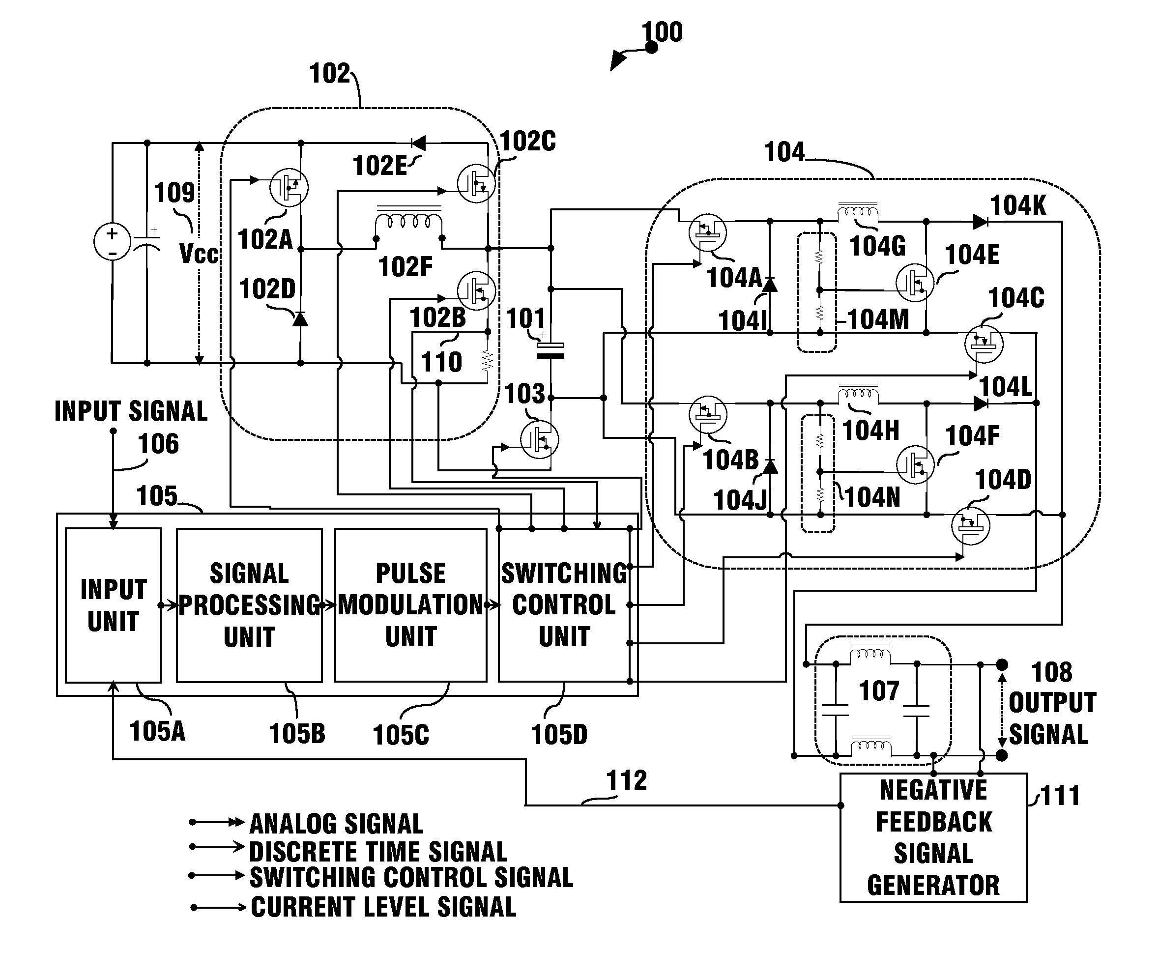
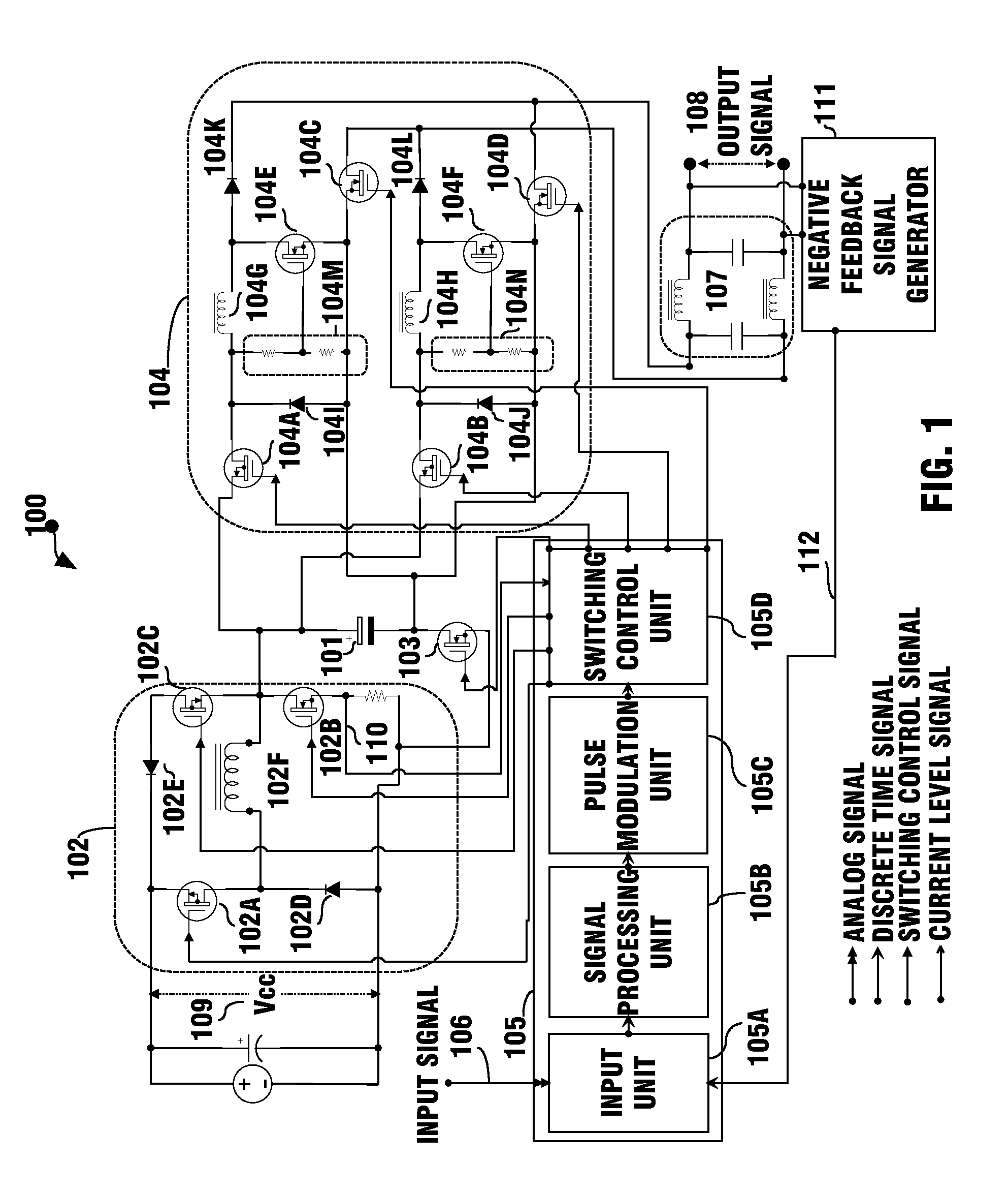
[0026]FIG. 1 is an exemplary block and circuit diagram illustrating an embodiment of a switching amplifier 100 in accordance with the first method of present invention, wherein the capacitor means 101 is a capacitor.

[0027]As illustrated in FIG. 1, the switching amplifier 100 of the present invention for amplifying an input signal 106 having positive and negative polarities is comprised of: a capacitor means 101; a current regulator unit 102 comprising switches 102A, 102B, 102C, diodes 102D, 102E and an inductor 102F for supplying a direct current (DC) constant current to the capacitor means 101 from a direct current (DC) voltage 109; a switching unit 103 for switching the constant current from the current...


PUM


Abstract

A switching amplifying method or a switching amplifier for obtaining a linearly amplified replica of an input signal, is highly efficient, and does not have the disadvantage of “dead time” problem related to class D amplifiers. Another aspect of the present invention provides a switching amplifier that is completely off when there is no input signal. Yet another aspect of the present invention further comprises an act of comparing an input signal with an output feedback signal for detection and correction of overall system signal processes therefore does not require a power supply regulator and is substantially immune to power supply and load perturbations.

Description

BACKGROUND OF THE INVENTION[0001](1) Field of the Invention[0002]This invention is related in general to a power amplifier, and more particularly, to a switching amplifier that can efficiently and linearly amplify an input signal having first and second polarities for obtaining a low-distortion output signal.[0003](2) Description of the Related Art[0004]Amplifiers are electronic devices which are used for increasing the power of a signal, and are generally categorized into various classes. The popular amplifiers include class A, class B and class D amplifiers. Reference is made to the exemplary U.S.Ppatents that disclose various types of amplifiers: U.S. Pat. Nos. 7,952,426; 7,816,985; 7,400,191; 7,286,008; 6,922,101; 6,794,932; 6,563,377; 6,356,151; 6,282,747; 5,949,282; 5,805,020; 5,767,740; 5,160,896; 5,115,205; 5,014,016; 4,531,096 and 3,629,616.[0005]In general, class A amplifiers produce a linearly amplified replica of an input signal, but are inefficient in terms of power usa...

Claims


Application Information

Patent Timeline
Patent Type & Authority Patents(United States)
IPC IPC(8): H03F3/38
CPCH03F1/342H03F3/2171H03F3/2175
Inventor HSIEH, WEN-HSIUNG
Owner HSIEH WEN HSIUNG
Why Eureka
Try Eureka