High-strength microwave antenna coupling

a microwave antenna and high-strength technology, applied in the direction of screws, threaded fasteners, bolts, etc., can solve the problems of unwanted heating of healthy tissue, non-invasive use of microwave energy requires a great deal of control, and the thermal damage of most types of normal cells is routinely observed, so as to achieve the effect of adding strength to the thin region

Inactive Publication Date: 2012-08-21
TYCO HEALTHCARE GRP LP
View PDF144 Cites 27 Cited by
  • Summary
  • Abstract
  • Description
  • Claims
  • Application Information

AI Technical Summary

Benefits of technology

[0015]At least two benefits may be realized by dissociating the dielectric member from the coupling member as described herein. First, by providing a coupling member that is discrete from the dielectric member, the coupling member may be able to absorb stresses imposed thereupon, rather than transmit such stress into the dialectic member. Second, the disclosed arrangement permits the use of materials that are better-suited to their function, for example, the dielectric member may be formed of porcelain while the coupling member may be formed of stainless steel. Continuing with the present example, porcelain may be well suited as a dielectric member because of its excellent insulative properties, yet may be poorly suited as a coupling member due to its brittleness. Conversely, stainless steel may be well-suited as a coupling member because of its toughness and strength, yet is electrically conductive therefore unsuitable as a dielectric. The present disclosure provides a coupler that advantageously combines the benefits of these materials without the drawbacks of either material.
[0018]The sleeve portion may include at least one longitudinal rib that is configured to engage a corresponding slot in the threaded coupling member. In this arrangement, the rib may serve to limit or prevent movement of the coupling member with respect to the insulating member arising from, for example, torque applied to the coupling member during antenna assembly.
[0020]In embodiments, the coupling portion may include a generally cylindrical reinforcing collar which extends into a corresponding cylindrical recess provided by the insulating member. The reinforcing collar may add strength to thinner regions of the insulating member, and may additionally distribute stresses to thicker regions of the insulating member.

Problems solved by technology

However, this non-invasive procedure may result in the unwanted heating of healthy tissue.
Thus, the non-invasive use of microwave energy requires a great deal of control.
However, at slightly elevated temperatures above the approximate range of 43° C. to 45° C., thermal damage to most types of normal cells is routinely observed.
However, many types of malignancies are difficult to reach and treat using non-invasive techniques or by using invasive antenna probes designed to be inserted into a normal body orifice, i.e., an easily accessible body opening.
These types of conventional probes may be more flexible and may also avoid the need to separately sterilize the probe; however, they are structurally weak and typically require the use of an introducer or catheter to gain access to within the body.
Moreover, the addition of introducers and catheters necessarily increase the diameter of the incision or access opening into the body thereby making the use of such probes more invasive and further increasing the probability of any complications that may arise.
However, such rigid, needle-like probes may experience difficulties in failing to provide uniform patterns of radiated energy; and may fail to provide uniform heating axially along and radially around an effective length of the probe.
Accordingly, it may be difficult to otherwise control and direct the heating pattern when using such probes.
Additionally, a dielectric junction used to separate portions of a rigid probe may be subjected to bending, compression, and rotational forces during manufacture, and during use.
These forces may lead to failure of the junction, particularly where the dielectric junction includes an integrally formed coupling member, such as a threaded or ribbed section.
Such threads or ribs often have edges which may cause stress concentrations induced by manufacturing or operational forces, causing mechanical or electrical failure of the dielectric junction.
This effect is exacerbated by the structural properties of suitable dielectric materials, such as porcelain or other ceramic materials, which tend to be brittle.
Continuing with the present example, porcelain may be well suited as a dielectric member because of its excellent insulative properties, yet may be poorly suited as a coupling member due to its brittleness.
Conversely, stainless steel may be well-suited as a coupling member because of its toughness and strength, yet is electrically conductive therefore unsuitable as a dielectric.

Method used


Image

  • High-strength microwave antenna coupling
  • High-strength microwave antenna coupling
  • High-strength microwave antenna coupling

Examples


Embodiment Construction

[0047]Particular embodiments of the present disclosure will be described herein with reference to the accompanying drawings. As shown in the drawings and as described throughout the following description, and as is traditional when referring to relative positioning on an object, the term “proximal” refers to the end of the apparatus that is closer to the user and the term “distal” refers to the end of the apparatus that is further from the user. In the following description, well-known functions or constructions are not described in detail to avoid obscuring the present disclosure in unnecessary detail.

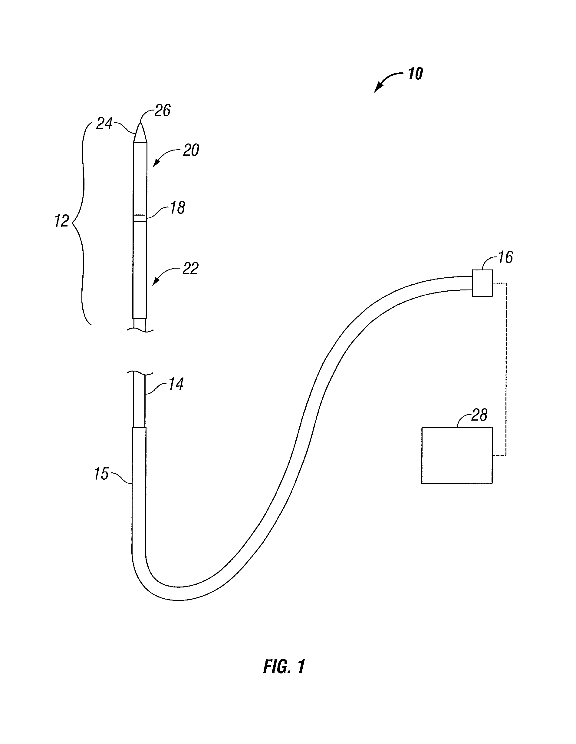
[0048]FIG. 1 shows an exemplary embodiment of a microwave antenna assembly 10 in accordance with the present disclosure. The antenna assembly 10 includes a radiating portion 12 that is connected by feedline 14 (or shaft) via cable 15 to connector 16, which may further connect the assembly 10 to a power generating source 28, e.g., a generator. Assembly 10, as shown, is a dipole microwa...


PUM


Abstract

Microwave antenna assemblies incorporating a high-strength antenna coupler are described herein. The microwave antenna has a radiating portion connected by a feedline to a power generating source, e.g., a generator. Proximal and distal radiating portions of the antenna assembly are separated by a microwave antenna coupler. In embodiments, the described antenna coupler includes a dielectric member and at least one discrete coupling member. The coupling member isolates coupling forces, such as tension and torque, from the dielectric member, which may prevent cracking and reduce the incidence of mechanical failure of the dielectric. The coupling member may be formed from high strength materials, such as stainless steel, allowing greater coupling forces to be achieved when compared to couplers using only dielectric materials. The coupling member may additionally include reinforcing members which extend into the dielectric member for increased strength.

Description

CROSS-REFERENCE TO RELATED APPLICATIONS[0001]This application claims the benefit of priority to U.S. Provisional Application Ser. No. 61 / 045,678 entitled “HIGH-STRENGTH MICROWAVE ANTENNA COUPLING” filed Apr. 17, 2008 by Arnold V. DeCarlo, which is incorporated by reference herein.BACKGROUND[0002]1. Technical Field[0003]The present disclosure relates generally to microwave surgical devices having a microwave antenna which may be inserted directly into tissue for diagnosis and treatment of diseases. More particularly, the present disclosure is directed to an insulated coupler for coupling the distal and proximal elements of a microwave antenna.[0004]2. Background of Related Art[0005]In the treatment of diseases such as cancer, certain types of cancer cells have been found to denature at elevated temperatures (which are slightly lower than temperatures normally injurious to healthy cells). These types of treatments, known generally as hyperthermia therapy, typically utilize electromagn...

Claims


Application Information

Patent Timeline
Patent Type & Authority Patents(United States)
IPC IPC(8): A61B18/18F16B39/02
CPCA61B18/18A61B18/1815A61B2017/00477
Inventor DECARLO, ARNOLD V.
Owner TYCO HEALTHCARE GRP LP
Why Eureka
Try Eureka