Forced convection target assembly

a force-convection and target technology, applied in the direction of reactor fuel elements, separation processes, particle separator tubes, etc., can solve the problems of high cost, high maintenance and operation costs, and high cost of high-skilled technical staff, so as to increase the beam yield and increase the heat transfer

Inactive Publication Date: 2012-08-21
ADVANCED APPLIED PHYSICS SOLUTIONS
View PDF18 Cites 3 Cited by
  • Summary
  • Abstract
  • Description
  • Claims
  • Application Information

AI Technical Summary

Benefits of technology

[0013]The invention provides a modified target assembly in which the target fluid is moved within the target assembly in a manner that increases the effective density of the target fluid within the beam path, thereby increasing beam yield. As detailed below, the invention utilizes forced convection, and optional structures arranged within the target envelope, to direct the target fluid within an inner sleeve in a direction opposite the direction of the beam current, i.e., produce a counter current flow of the target fluid, and optionally direct the flow of the target fluid toward a central region. This countercurrent flow of the target fluid suppresses, to some degree, the natural convective effects that tend to reduce the effective density of the target fluid within the beam path as a result of fluid heating and tend to increase the heat transfer from the target, allowing operation at lower temperatures and / or pressures.

Problems solved by technology

The systems used for generating the energetic charged particle beams, such as cyclotrons, electrostatic accelerators and radiofrequency quadrupoles, are typically expensive (usually more than US$1,000,000) to purchase, expensive to maintain and to operate and require highly skilled technical staff.
In some cases, the preferred target material may also be expensive to purchase, such as enriched 18O gas (typically more than US$500 per liter) and enriched 18O water (typically more than US$100 per milliliter).
An additional factor affecting the process yield is that the incoming charged particle beam tends to lack spatial uniformity with respect to particle distribution.
This means that the particle distribution within the beam is biased toward a central portion of the beam and the convective movement of the target gas will tend shift the target nuclei to areas within the target assembly that are exposed to fewer beam particles, thereby tending to decrease production of the desired product isotope(s).
As a result, even closely matching the configuration of the target chamber to the beam shape will generally not fully counteract the heating induced density reduction of the target gas in the higher beam density regions.
Further, target assemblies in which the target chamber includes little or no volume that is not within the beam strike region tend to experience much greater pressure increases than targets that include substantial target chamber volume that is not within the beam strike region.

Method used


Image

  • Forced convection target assembly
  • Forced convection target assembly
  • Forced convection target assembly

Examples


Embodiment Construction

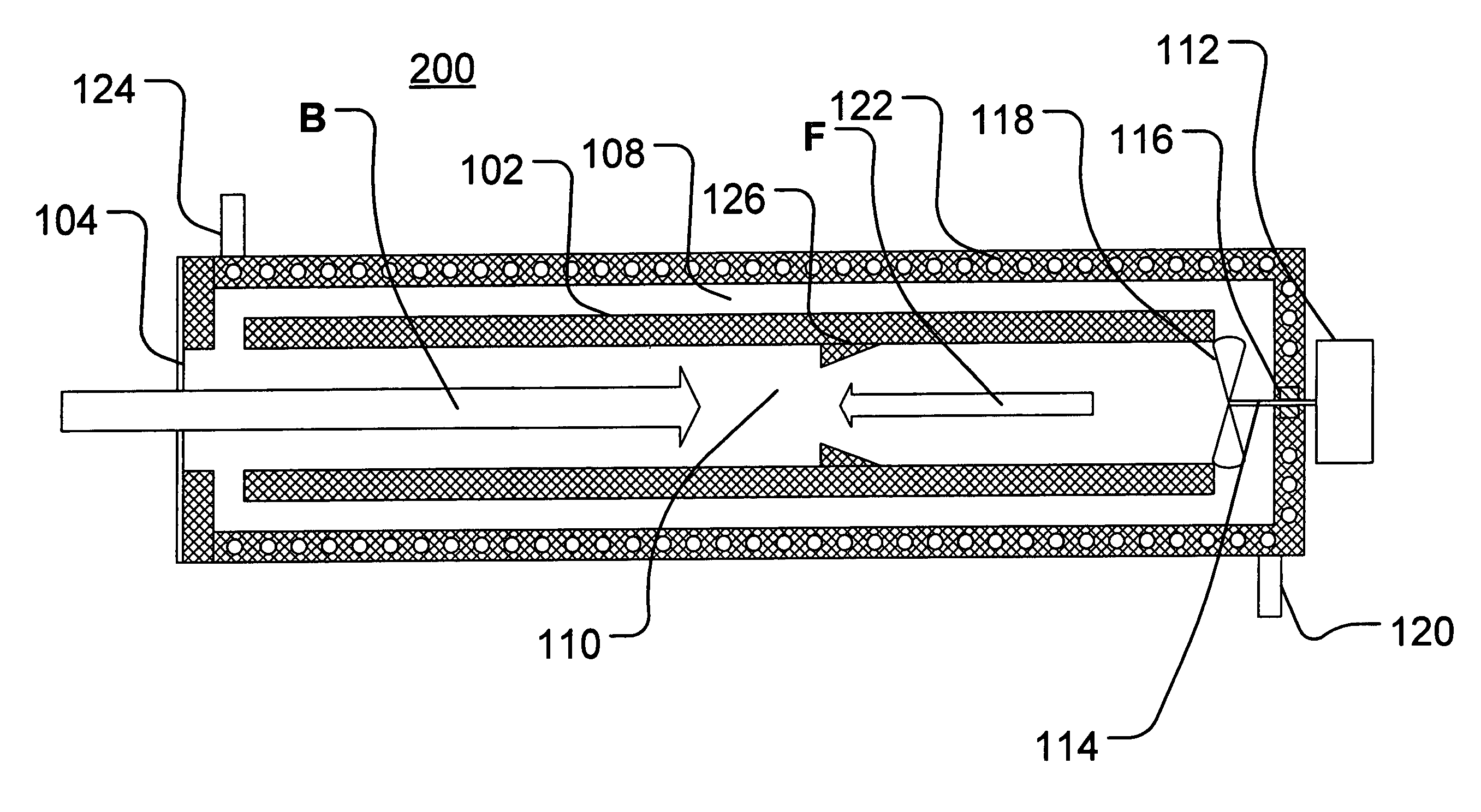
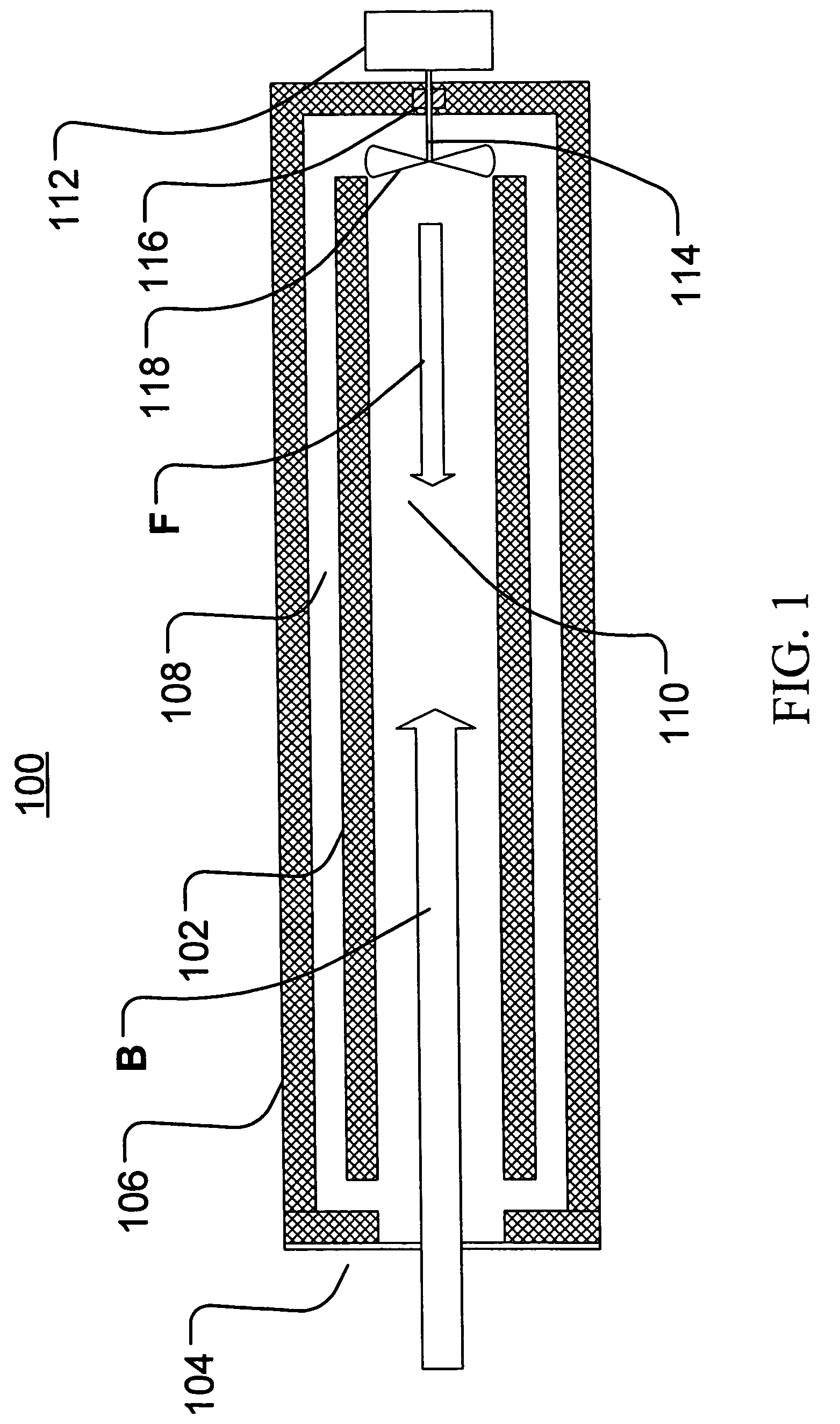
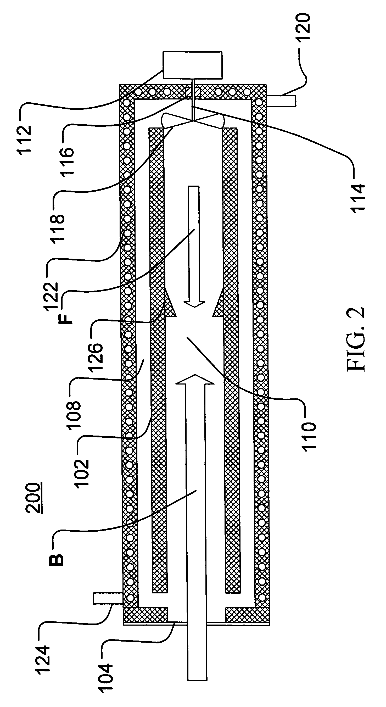
[0022]The particle beam must enter the target, preferably with as little energy loss as possible. The particle beam generation (in the accelerator) and transport to the target must occur in a vacuum to minimize the loss of particles. The high-pressure environment of the target must be isolated from this vacuum yet still allow the particle beam to enter the target chamber. One method of forming a beam window or port utilizes a pair of thin metal foils between which passes helium or another cooling gas to remove the heat produced in the foils by the passage of the particle beam. Another method of forming a beam window or port utilizes a single thin metal foil supported by a water cooled structure referred to as a grid as disclosed in U.S. Pat. No. 5,917,874, the contents of which are hereby incorporated in its entirety. This grid will, however, partially intercept the particle beam, thereby reducing the number of beam particles that will actually enter the target and reach the target ...


PUM


Abstract

Provided is a modified target assembly in which the target fluid is moved within the target assembly in a manner that increases the effective density of the target fluid within the beam path, thereby increasing beam yield utilizing forced convection. The target may also include optional structures, such as nozzles, diverters and deflectors for guiding and / or accelerating the flow of the target fluid. The target assembly directs the target fluid along an inner sleeve in a direction opposite the direction of the beam current to produce a counter current flow and may also direct the flow of the target fluid away from the inner surface of the inner sleeve and toward a central region in the target cavity. This countercurrent flow suppresses natural convection that tends to reduce the density of the target fluid in the beam path and tends to increase the heat transfer from the target.

Description

PRIORITY STATEMENT[0001]This application claims priority from U.S. Provisional Patent Application No. 60 / 583,433, filed Jun. 29, 2004, the contents of which are hereby incorporated herein by reference in their entirety.BACKGROUND OF THE INVENTION[0002]The production of radioisotopes typically involves irradiating a target fluid (gas or liquid) maintained within a target assembly with an energetic charged particle beam. The energetic charged particle beam may be characterized by one or more parameters such as particles per second, beam current (typically measured in microamps (μA) or milliamps (mA)), particle velocity, beam energy (typically measured in kilo electron volts (KeV) or mega electron volts (MeV)), and beam power (typically measured in watts (W)). The interaction of one of the energetic particles from the particle beam with a target nucleus in the target fluid will, under the appropriate conditions, tend to produce a nuclear reaction that transforms the target nucleus into...

Claims


Application Information

Patent Timeline
Patent Type & Authority Patents(United States)
IPC IPC(8): G21G1/10G21G1/00G21C19/42H01J49/00F28F7/00F25B41/06F25B39/02F25D23/12
CPCG21G1/10G21G4/00G21K1/10G21K5/08G21K5/10H05H6/00G21K5/00G21G1/00
Inventor BUCKLEY, KENNETH ROBERT
Owner ADVANCED APPLIED PHYSICS SOLUTIONS
Why Eureka
Try Eureka