Stop flow interference lithography system

a lithography system and flow interference technology, applied in the field of stop flow interference lithography system, can solve the problems of imposing restrictions on the shape and material properties of the structure formed, the type and geometry of the structure that can be formed, and the defects of the face, so as to achieve high throughput, improve throughput, and low viscosity

Active Publication Date: 2012-08-28
MASSACHUSETTS INST OF TECH
View PDF9 Cites 50 Cited by
  • Summary
  • Abstract
  • Description
  • Claims
  • Application Information

AI Technical Summary

Problems solved by technology

Bottom-up approaches like polymer phase separation,[8] molecular self-assembly,[9] or colloidal assembly[10] are cheap and can cover large areas but face problems of defects and limitations in the type and the geometry of structures that can be formed.
While top-down methods offer precise size and shape control, the need to construct the 3D structures using either a point-by-point or layer-by-layer process makes such methods as gray-scale photolithography,[11] direct 3D writing,[12] or 2-photon lithography[13] very time consuming.
However, phase mask interference lithography (PMIL)[16,17] is typically performed by flood exposing a spin-coated layer of photoresist film through a phase mask, thus imposing some restrictions on the shape and material properties of the structures formed as well as limiting the throughput because of the serial nature of the processing.
Furthermore, such processes are not easily amenable to the fabrication of structures that possess chemical anisotropy.
However, to date, the use of transparency masks has restricted the method to the formation of only solid 2D shapes with relatively large feature sizes.[22,25]

Method used


Image

  • Stop flow interference lithography system
  • Stop flow interference lithography system
  • Stop flow interference lithography system

Examples


Embodiment Construction

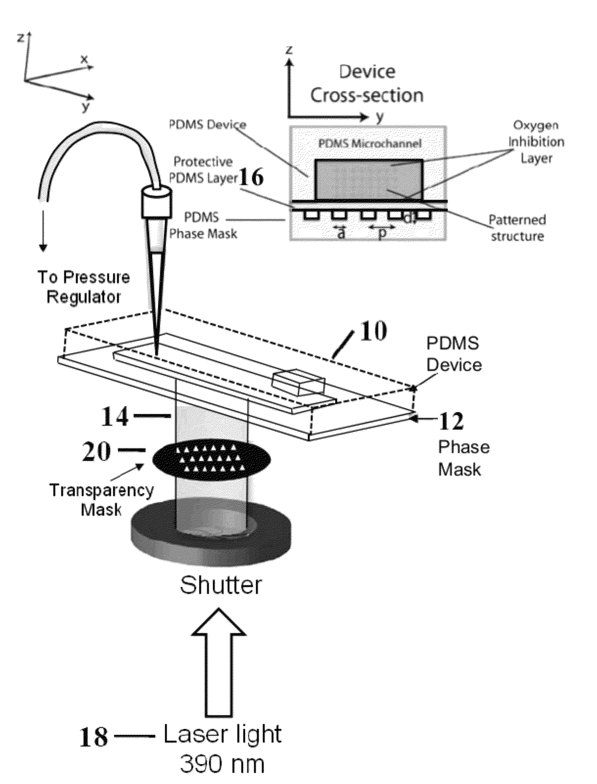
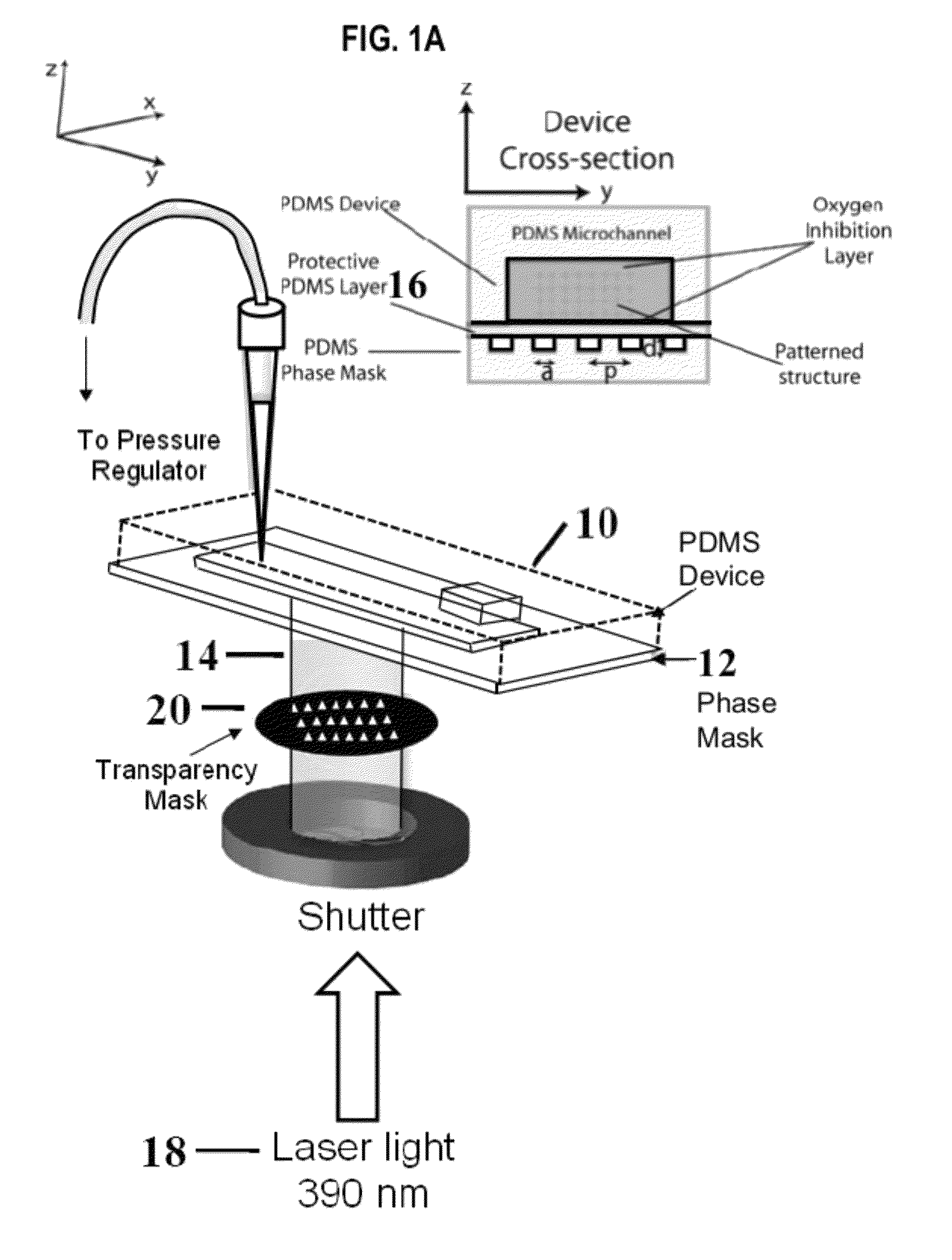
[0022]A schematic diagram of the setup used for SFIL is shown in FIG. 1. The microfluidic device 10 and a phase mask 12, both molded in PDMS, are sealed to each other as shown in the cross-sectional view in FIG. 1a. The passage of collimated light 14 through the phase mask 12 results in the generation of a complex 3-dimensional distribution of light intensity. This induces crosslinking of the oligomer only in the high intensity regions leading to the formation of a 3D structure. A protective, 3 μm thick, PDMS layer 16 is laminated (as by spin-coating) on top of the phase mask 12 in order to prevent the liquid oligomer from filling up the interstitial spaces in the phase mask 12 that provide the refractive index difference required when light traverses through the phase mask. We have used microfluidic devices with a lateral dimension of 1-5 mm to synthesize both millimeter-sized structures as well as arrays of micron-sized particles. The integrated device is placed on a microscope st...


PUM

PropertyMeasurementUnit
thickaaaaaaaaaa
thicknessaaaaaaaaaa
thicknessaaaaaaaaaa

Abstract

Stop flow interference lithography system for high throughput synthesis of 3-dimensionally patterned polymer particles. The system includes a microfluidic channel containing a stationary oligomer film and a phase mask located adjacent to the microfluidic channel. A source of collimated light is provided for passing the collimated light through the phase mask and into the microfluidic channel for interaction with the oligomer. The passage of the collimated light through the phase mask generates a 3-dimensional distribution of light intensity to induce crosslinking of the oligomer in high intensity regions thereby forming 3-dimensional structures.

Description

[0001]This application claims priority to U.S. provisional patent application Ser. No. 61 / 081,864 filed on Jul. 18, 2008, the contents of which are incorporated herein by reference in their entirety.[0002]This invention arose from research supported by the U.S. Army Research Office under grant numbers W911NF-07-D-0004 and DAAD-19-02-D-0002. The government has certain rights in this invention.BACKGROUND OF THE INVENTION[0003]This invention relates to a stop flow interference lithography system and more particularly to such a system for the high throughput synthesis of 3-dimensionally patterned polymeric particles.[0004]Polymeric structures with repeating 2-dimensional (2D) and 3D motifs at the micron scale and below have a variety of uses. Patterned 2D structures have been shown to have myriad applications in biosensors,[1] tissue engineering,[2] and diagnostic assay systems.[3] The numbers in brackets refer to the references included herein. The contents of all of these references a...

Claims


Application Information

Patent Timeline
Patent Type & Authority Patents(United States)
IPC IPC(8): G03F7/20
CPCG03B27/54G03F7/2012G03F7/2035G03F7/40G03F7/027
Inventor THOMAS, EDWIN L.DOYLE, PATRICK SEAMUSDENDUKURI, DHANANJAYJANG, JI-HYUNULLAL, CHAITANYA K.
Owner MASSACHUSETTS INST OF TECH
Why Eureka
Try Eureka