Orbiting drum wind turbine and method for the generation of electrical power from wind energy

a technology of wind turbines and wind energy, which is applied in the direction of propellers, water-acting propulsive elements, energy industry, etc., can solve the problems of insufficient supply of oil, natural gas or coal, insufficient use of wind energy for electricity generation, and inability to meet the needs of the environment, etc., to achieve low cost, reduce susceptibility to failure, and compact design

Inactive Publication Date: 2012-08-28
BECKER ERWIN MARTIN
View PDF75 Cites 14 Cited by
  • Summary
  • Abstract
  • Description
  • Claims
  • Application Information

AI Technical Summary

Benefits of technology

[0008]It is therefore an object of the invention to provide an orbiting drum turbine with drums in an extremely compact design, and with a considerably reduced susceptibility to failure that can be produced and operated inexpensively and with a high degree of efficiency.
[0010]Place a pencil on a sheet of paper on a desk and blow on it from random angles, and at varying strength. The invention comprises transferring the thus created rolling motion demonstrated by the pencil example to a continuous loop, and using it to generate energy. In comparison, the three-blade rotor of a conventional wind turbine with a diameter of 80 m renders the same power output as 20 drum turbines with a length of 6 m. The drums, or drive elements, are driven by both impact pressure and by the Magnus effect. The Magnus effect, achieved partially as a result of fluid passing a spinning drum, potentially provides significant enhancement of the efficiency of the system. According to Prof. Ludwig Prandtl of the University of Göttingen, the Magnus-Effect renders up to ten times more uplift than an airfoil.
[0015]According to still another embodiment of the invention, an orbiting drum wind turbine for capturing energy from a flowing fluid medium spins the drive element as it follows the orbiting course using a movable flexible drive member, for example a toothed belt or a chain such as a double-roller chain, that engages at least one drive element drive wheel mounted on the drive element. There is also a stationary drive surface in contact with the drive element drive wheel and mounted on the base. The stationary surface is designed to grip the surface of the drive element wheel, permitting the drive element wheel to roll along over the stationary surface but preventing the drive element wheel from slipping on the stationary surface. The stationary drive surface can be a gear rack that mates with a drive element cog wheel.
[0018]Another embodiment of the invention comprises at least one drum-shaped drive element having a reinforcing spiral-shaped corrugated outer layer. This is so that as the drive element spins, any Magnus effect present will be enhanced.
[0019]According to another embodiment of the invention, an orbiting drum wind turbine for capturing energy from a flowing fluid medium has support, a rotary crane mounted on the support for following the direction of flow of the fluid medium, a forked crown mounted on the rotary crane and a swing carrier mounted in the forked crown. The swing carrier supports the base. The base can be pivoted from the swing carrier in the forked crown, thereby varying the attitude of the base to match the flow speed of the fluid medium. At low flow speeds the base is tilted toward the vertical to present a larger profile to the fluid medium. At higher flow speeds, the base is tilted to a flatter configuration, thereby presenting a small profile to the flowing medium. This is so that during high flow speed conditions the apparatus can be throttled by tilting to maximize performance by varying the angle of incidence of the fluid medium on the base.
[0023]According to still another embodiment of the invention, an orbiting drum wind turbine for capturing energy from a flowing fluid medium has a rotary crane mounted on a support for following the direction of flow of the flowing fluid medium. Mounted on the rotary crane is a forked crown. A swing carrier supporting the base is mounted in the forked crown. The base can be pivoted from the swing carrier in the forked crown, thereby varying the attitude of the base to match the flow speed of the fluid medium, so that during high speed conditions the apparatus can be throttled by tilting to maximize performance by varying the angle of incidence of the wind on the base.

Problems solved by technology

The supply of oil, natural gas, or coal, as resources for generation of energy is eventually limited, and will be too expensive to use for this purpose in the foreseeable future.
In addition, the detrimental consequences of the combustion of oil, gas, and coal for the environment are sufficiently known.
However, these wind turbines also have disadvantages: if operated in the vicinity of populated areas, inhabitants are harassed by noise and shadows cast.
In addition, equipment losses due to bird strikes have been reported.
A particular hazard for large wind power plants is lightning strikes.
Cases are known where despite lightning protection systems, rotor blades have been struck by lightning and were destroyed.
In other cases, the electric control was destroyed by lightning, or fire has destroyed the entire plant.
However, slenderness of profile in very large rotor blades is limited by statics.
It is known that due to differences in wind speed, resonance oscillations may build up and lead to material fatigue.
In the worst case, this can lead to physical contact of the blades with the tower and rupture of the blade.
In addition, the passing of the blade at the tower creates objectionable noise and can, with both windward and leeward rotors, lead to resonance oscillations.
One disadvantage is the chain drive.
Additionally, the Magnus-Effect is not applicable in the context of Cocjin's construction principle.
It is general knowledge that chains undergo material extension, create operational noise, and need extensive care.
Moreover, Cocjin's machine cannot adjust to different wind velocities, because it lacks run control.
As a consequence, the machine has to be shut off at higher wind velocities.

Method used


Image

  • Orbiting drum wind turbine and method for the generation of electrical power from wind energy
  • Orbiting drum wind turbine and method for the generation of electrical power from wind energy
  • Orbiting drum wind turbine and method for the generation of electrical power from wind energy

Examples


Embodiment Construction

[0043]The present invention will now be described in detail. The figures are illustrative examples of the invention presented to enable those skilled in the art to practice the invention. These figures and examples are not meant to limit the scope of the present invention to a single embodiment. Other embodiments can be implemented by interchanging some of the described or illustrated elements and by using equivalent structures.

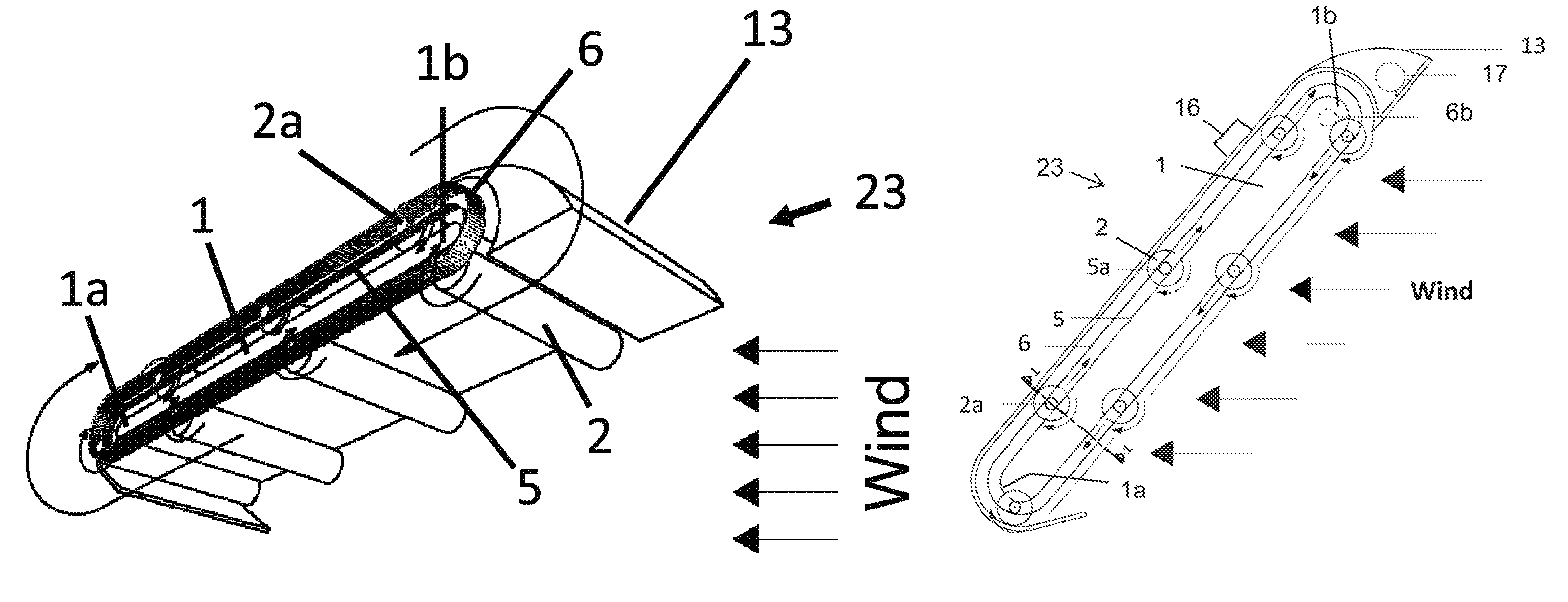
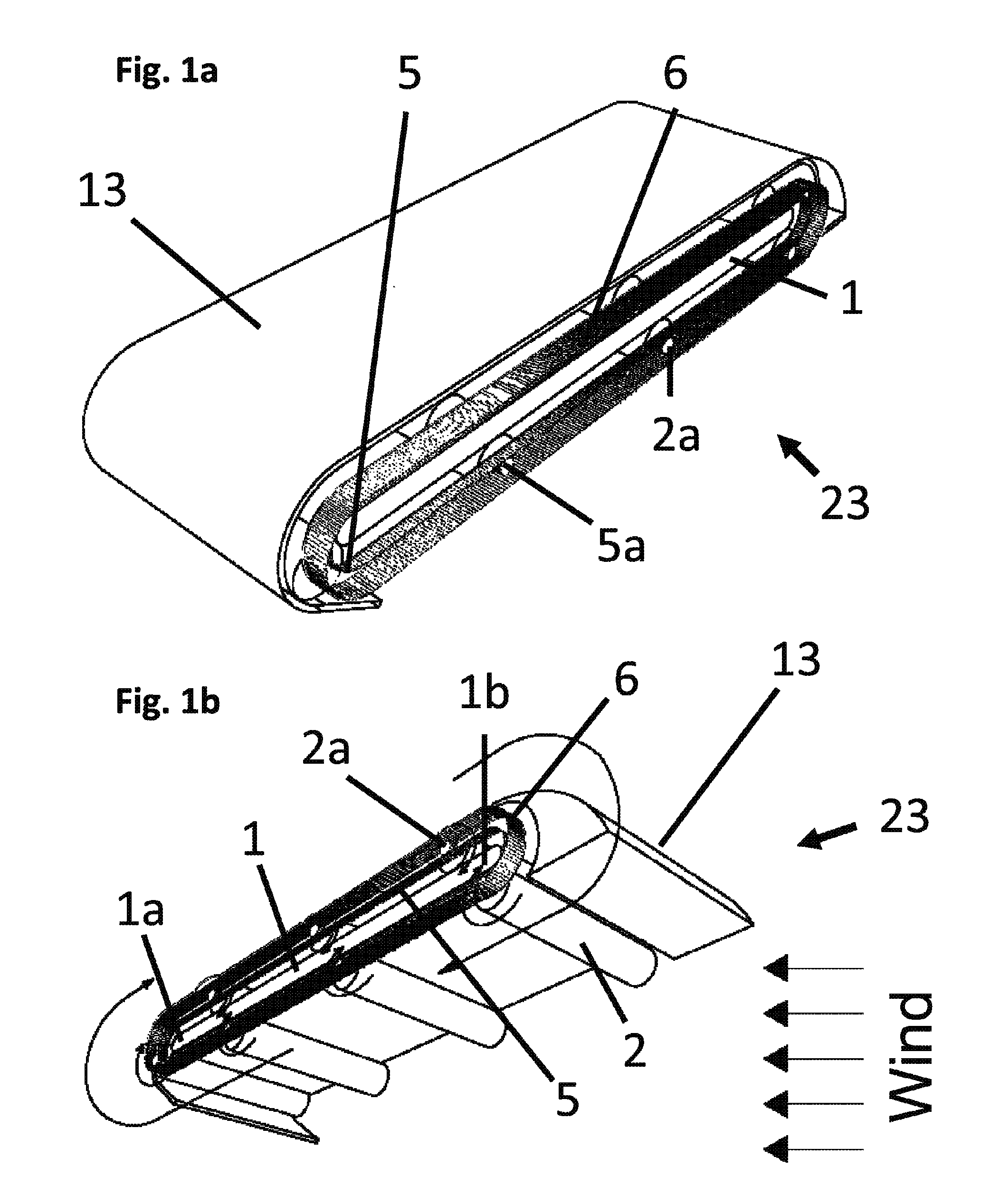
[0044]First the linear motion of the drive elements will be described, followed by the means for guiding the drive elements in their courses as they travel around a continuous orbiting course. Then the means for spinning the drive elements will be discussed, followed by a discussion of the apparatus for transferring energy from the drive elements. Finally, additional features of the apparatus will be explained.

[0045]The linear motion of the drive elements according to one embodiment is illustrated in FIG. 1a and FIG. 1b, which show two partial perspective vie...


PUM


Abstract

A wind turbine captures energy from a flowing fluid medium using drum-shaped drive elements that spin while traveling along a continuous orbiting course around a base. Attached roller bearings engaging stationary raceways can guide the drive elements. Means for spinning the drive elements can include toothed belts engaging drive element cog wheels. Spinning can provide Magnus effect enhancement. Wind energy is captured by the drive element motion, then transferred to the base cog wheels by a toothed belt and finally fed to an output shaft. The invention includes locating drive elements in a moving fluid medium, spinning the drive elements as they are urged by the wind along a continuous orbiting course and capturing energy by linking the motion of the drive elements to an external device. The method includes adjusting the base's azimuth and the angle of incidence of the wind in response to wind direction and speed.

Description

CROSS-REFERENCE TO RELATED APPLICATIONS[0001]This application claims priority to German Patent Application DE 10 2010 008 061.6 filed on Feb. 16, 2010, and incorporated herein by reference in its entirety.BACKGROUND OF THE INVENTION[0002]The present invention is related to extracting power from moving fluids such as wind and water. Application examples include, but are not limited to, powering water pumps, process machinery and prime-mover dynamo plants having an integrated or external dynamo driven by a fluid current motor.[0003]The supply of oil, natural gas, or coal, as resources for generation of energy is eventually limited, and will be too expensive to use for this purpose in the foreseeable future. In addition, the detrimental consequences of the combustion of oil, gas, and coal for the environment are sufficiently known.[0004]The invention is designed to contribute to the protection of the environment, by using wind energy.[0005]Wind turbines with a horizontal axis and a thr...

Claims


Application Information

Patent Timeline
Patent Type & Authority Patents(United States)
IPC IPC(8): F03B13/00H02P9/04F03D9/00
CPCF03D5/02F05B2240/13F05B2240/201F05B2240/2212F05B2260/403Y02E10/70Y02P80/10
Inventor BECKER, ERWIN MARTIN
Owner BECKER ERWIN MARTIN
Why Eureka
Try Eureka