
Riding apparatus for treating floor surfaces with a power cord handling swing arm

a technology of power cord and floor surface, which is applied in the direction of grinding drives, grinding machine components, manufacturing tools, etc., can solve the problems of concrete inherently producing dust particles from constant scuffing, rough exterior surface of newly poured concrete floor, and uneven surface once dry,

Active Publication Date: 2012-09-11
ONFLOOR TECH
View PDF16 Cites 3 Cited by
  • Summary
  • Abstract
  • Description
  • Claims
  • Application Information

AI Technical Summary

Benefits of technology

Enhances operator safety and visibility, simplifies power cord handling, allows for easier maintenance of grinding tools, and improves dust control by providing a comprehensive solution for floor surface treatment.

Problems solved by technology

However, the exterior surface of a newly poured concrete floor, once dry, is often rough, uneven, and provides a dull appearance.
Furthermore, when left in this unfinished state, the concrete will inherently produce dust particles from the constant scuffing, whether it is from foot traffic or wheeled traffic that can build over time and become a nuisance to those who work and / or live in these environments.
These walk along configurations can produce fatigue in the operator and the operator's position behind the machine prevents a clear view of the floor surface until the floor surface passes under the operator's feet well behind the deck.
Thus if a spot on the floor is missed or not adequately prepared, the operator may need to back up a distance to redo the spot.
Firstly, some are large using standard tractor bodies powered by internal combustion gas, diesel or propane engines.
The exhaust from such gasoline, diesel or propane engines makes it less desirable to use within an interior confined space.
The use of internal combustion engines and hydraulic drive systems also introduces the significant probability that there may be leakage of oil, petroleum based or synthetic based lubricant or fluid onto a porous cured top layer of concrete or an even more porous substrate.
Any leakage or spillage of oil, gasoline diesel fuel or grease onto the surface will be readily and permanently absorbed into the concrete and leave a permanent stain that will never yield a proper polished surface free of stains.
Furthermore the oil, grease, or lubricant can contaminate the cutters or other grinding, and polishing pads or tools.
In addition, many of these machines are quite large and the operator has no view or a poor view of the floor after the deck passes over.
Thus on-the-spot quality control for just prepared floor surface is extremely difficult.
Riding polishing and cleaning machines have had awkward configurations with either rear positioned seating or enclosed cab seating for the operator which blocks his view.
Other machines have open high precarious seating which can make the operator feel vulnerable or unsafe in such a high open position from the floor.
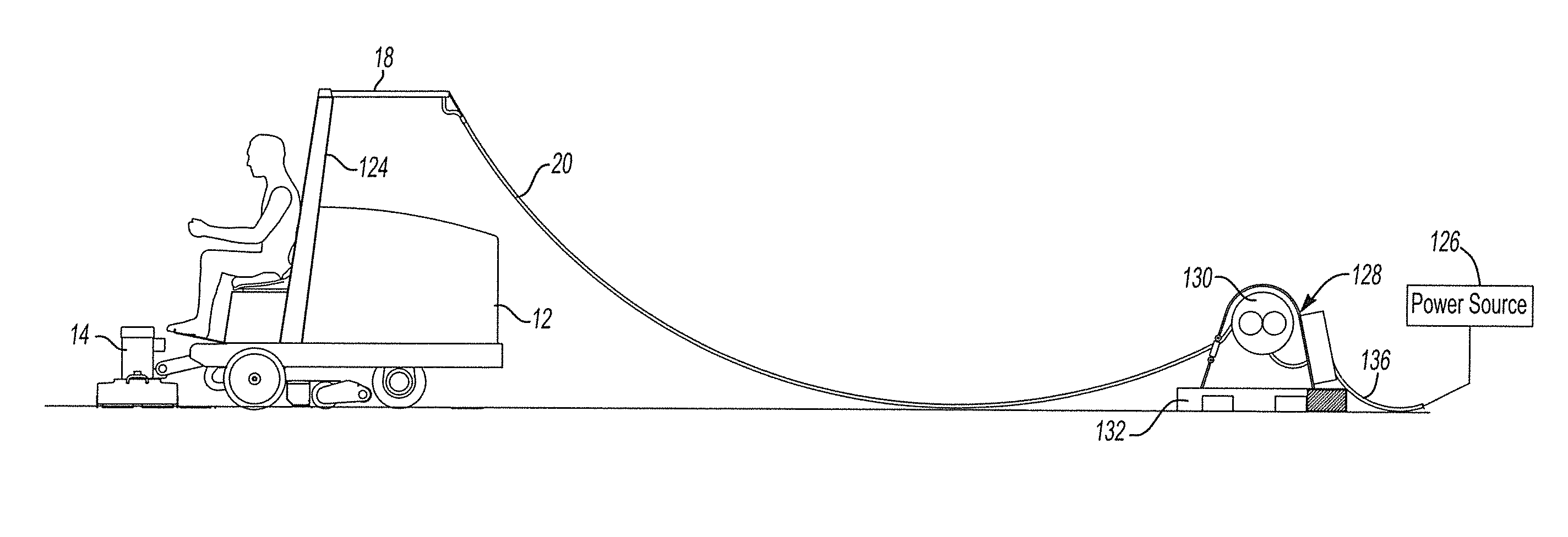
While the wheels and vehicular controls are powered by on board rechargeable batteries, the proper high pressure, torque and speed power needed for the cleaning and abrasive deck is too demanding for present day battery technology so the electric power is provided through a power cord from a remote power supply.
A significant amount of time is spent by the operator manually getting off the vehicle to move the cord out of the way of the vehicle.
Another difficulty with the known riding polishing and cleaning machines is the difficulty in changing the grit pads or cutters when the grit pads or cutters become worn.
Replacing the worn pads or cutters, or in some cases replacing the entire deck is both burdensome and time consuming to the user.
Another common problem is dust control.
As such when uneven flooring or an obstacle is encountered, the sweeping apparatus can be jammed or not provide the necessary ground clearance.

Method used


Image

  • Riding apparatus for treating floor surfaces with a power cord handling swing arm
  • Riding apparatus for treating floor surfaces with a power cord handling swing arm
  • Riding apparatus for treating floor surfaces with a power cord handling swing arm

Examples


Embodiment Construction

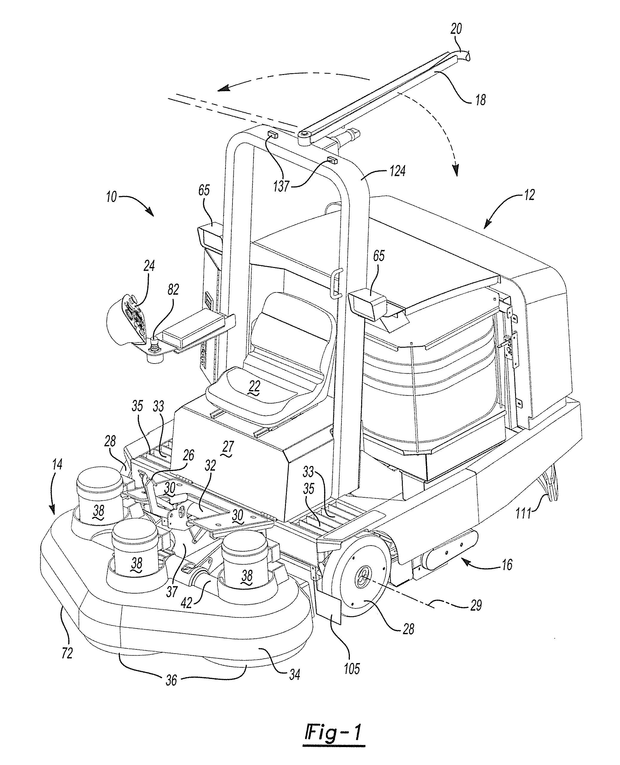
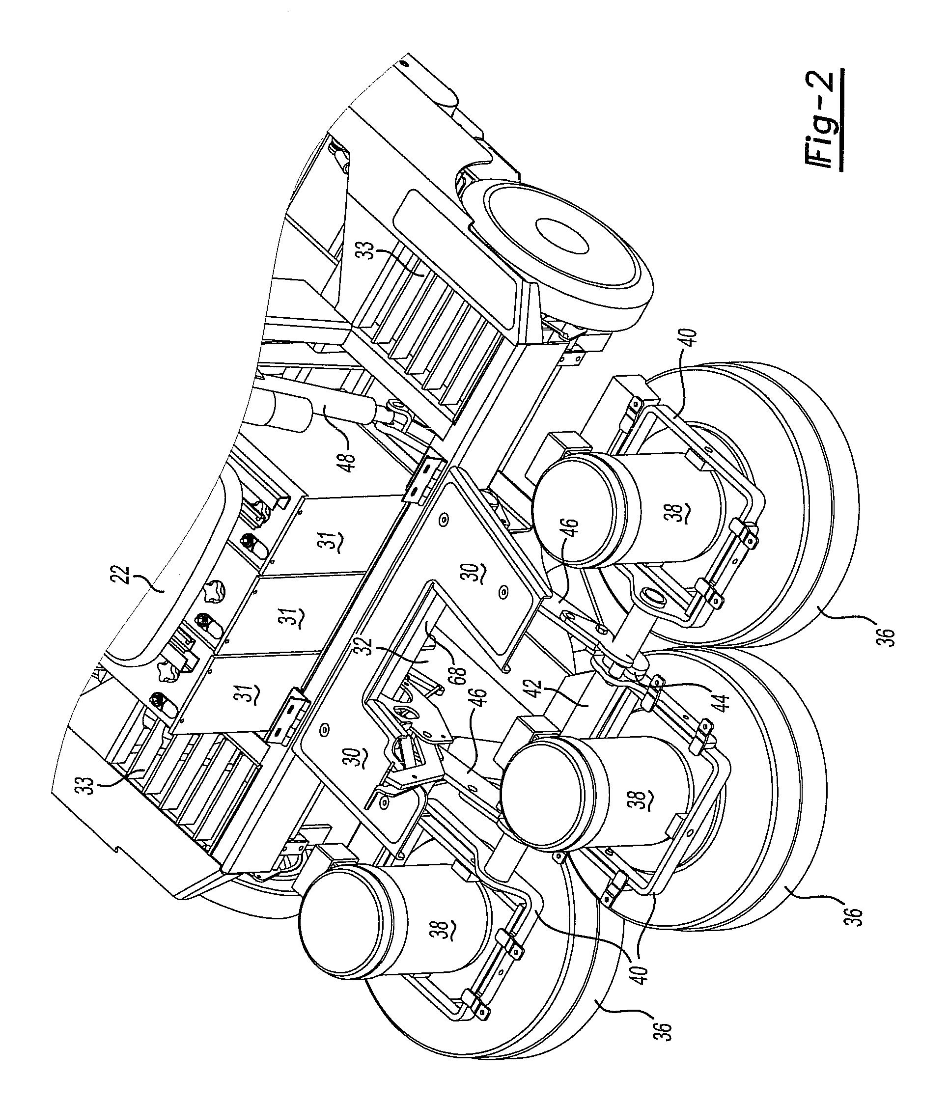
[0052]Referring now to FIG. 1, a riding apparatus 10 for treating floor surfaces has a battery operated main vehicle body 12, a forwardly positioned polishing and cleaning deck 14, a sweeping deck 16, and a swing arm 18 for a power cord 20.

[0053]The vehicle body 12 has a forward positioned operator seat 22 with controls 24 readily positioned for hand operation to control speed, direction and other needed vehicle and deck functions and foot controls 26, for example a brake and transmission clutch. The seat 22 is positioned over the electric batteries storage container 27. The electric batteries 31 stored in container 27 as shown in FIG. 3 can be conventional lead acid type or any state of the art battery that powers the vehicle motion. The seat 22 is also aligned above an axis 29 defined by the two front wheels 28.

[0054]Two foot rests 30 are positioned apart to rest the operator's left and right feet. A gap 32 is formed between the two foot rests 30. The gap 32 is aligned over the cl...


PUM


Abstract

A swing arm for managing a power cord to an electric vehicle has a proximate arm member with a pivotable connection about a vertical axis for connection to the vehicle in proximity to a longitudinal center line of the vehicle. A distal arm member is pivotably connected about a pivot vertical axis to the proximate arm member and resiliently biased to extend straight out with respect to the proximate arm member. The swing arm is dimensioned to extend the distal arm member beyond a side of the vehicle when the swing arm extends laterally with respect to the vehicle. A spring member is connected to the distal arm member for resiliently biasing the distal arm member to extend straight out with respect to the proximate arm member against a side force below a predetermined amount and yieldable to bending of the distal arm member upon exertion of a side force above the predetermined amount.

Description

CROSS REFERENCE TO RELATED APPLICATION[0001]This application is a continuation-in-part of pending PCT / US2008 / 000677 filed on Jan. 18, 2008.TECHNICAL FIELD[0002]The field of this invention relates to a riding apparatus for treating a floor surface with a power cord handling swing arm.BACKGROUND OF THE DISCLOSURE[0003]Concrete floors are common today in large, medium and small retail stores, manufacturing and production facilities, warehouses, automotive shops and service centers, shopping centers, garages, commercial buildings and residential basements as well as the common material for sidewalks. The strength of concrete provides the durability and rigidity required in these environments. However, the exterior surface of a newly poured concrete floor, once dry, is often rough, uneven, and provides a dull appearance. Furthermore, when left in this unfinished state, the concrete will inherently produce dust particles from the constant scuffing, whether it is from foot traffic or wheel...

Claims


Application Information

Patent Timeline
Patent Type & Authority Patents(United States)
IPC IPC(8): B24B23/00B24B21/18
CPCB24B7/186Y10T24/39
Inventor STRICKLAND, TIMOTHY ALAN
Owner ONFLOOR TECH
Learn More